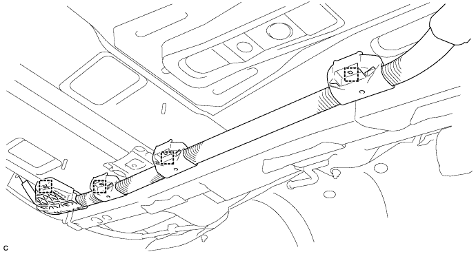
FRAME WIRE > REMOVAL |
| 1. PRECAUTION |
| 2. REMOVE SERVICE PLUG GRIP |
| 3. REMOVE TONNEAU COVER ASSEMBLY (w/ Tonneau Cover) |
Remove the tonneau cover assembly.
| 4. REMOVE REAR NO. 4 FLOOR BOARD (w/o Woofer) |
Remove the rear No. 4 floor board.
| 5. REMOVE REAR NO. 4 FLOOR BOARD (w/ Woofer) |
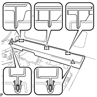 |
Disengage the 2 clips and 3 guides, and remove the rear No. 4 floor board.
| 6. REMOVE DECK FLOOR BOX LH (w/o Woofer) |
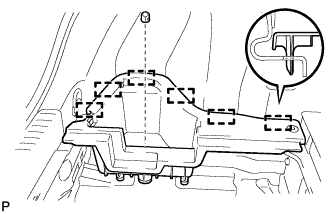 |
Remove the clip.
Disengage the 6 guides and remove the deck floor box LH.
| 7. REMOVE INVERTER WITH CONVERTER ASSEMBLY |
| 8. REMOVE FRONT EXHAUST PIPE ASSEMBLY |
| 9. REMOVE FRONT NO. 1 FLOOR HEAT INSULATOR |
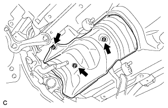 |
Remove the 3 nuts and front No. 1 floor heat insulator.
| 10. REMOVE FRONT FLOOR COVER RH (w/ Cover) |
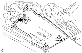 |
Remove the bolt
Remove the 4 clips and the front floor cover RH.
| 11. REMOVE FRONT CENTER FLOOR COVER RH (w/ Cover) |
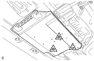 |
Remove the 3 clips and the front floor cover center RH.
| 12. REMOVE FRONT SUSPENSION MEMBER BRACE REAR RH |
Using a transmission jack, hold the front suspension cross member.
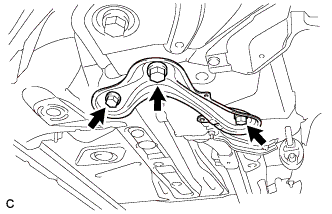 |
Remove the 3 bolts and front suspension member brace rear RH.
| 13. REMOVE REAR SEATBACK ASSEMBLY RH |
| 14. REMOVE REAR DOOR SCUFF PLATE RH |
| 15. REMOVE REAR SEAT SIDE GARNISH RH |
| 16. REMOVE REAR NO. 1 FLOOR BOARD SUB-ASSEMBLY |
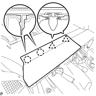 |
Disengage the 2 claws and 2 clips, and remove the rear No. 1 floor board sub-assembly.
| 17. REMOVE REAR NO. 2 FLOOR BOARD SUB-ASSEMBLY |
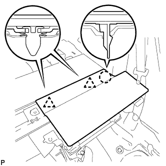 |
Disengage the claw and 2 clips, and remove the rear No. 2 floor board sub-assembly.
| 18. REMOVE REAR NO. 1 FLOOR BOARD |
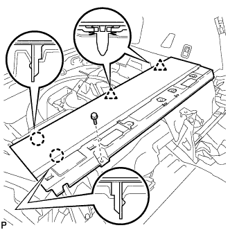 |
Remove the bolt.
Disengage the 2 claws and 2 clips, and remove the rear No. 1 floor board.
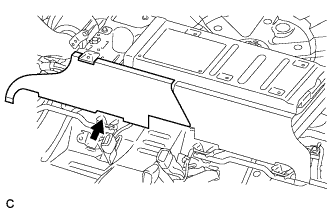
| 19. REMOVE HYBRID VEHICLE BATTERY SHIELD SHEET |
 |
| 20. REMOVE REAR FLOOR BOARD SPACER |
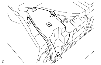 |
Remove the 2 clips and rear floor board spacer.
| 21. REMOVE NO. 1 HYBRID BATTERY INTAKE DUCT |
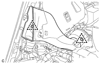 |
Remove the 2 clips and No. 1 hybrid battery intake duct.
| 22. REMOVE NO. 1 HYBRID BATTERY EXHAUST DUCT |
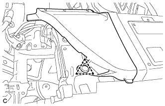 |
Remove the clip and No. 1 hybrid battery exhaust duct.
| 23. REMOVE UPPER HYBRID BATTERY COVER SUB-ASSEMBLY |
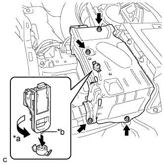 |
Using the service plug grip, remove the battery cover lock striker.
| *a | Turn |
| *b | Projection |
Remove the 4 nuts and upper hybrid battery cover sub-assembly.
| 24. DISCONNECT CABLE FROM AUXILIARY BATTERY TERMINAL |
Remove the connector cover.
 |
Disconnect the clamp, and remove the nut.
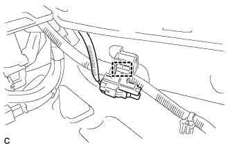 |
Disconnect the clamp.
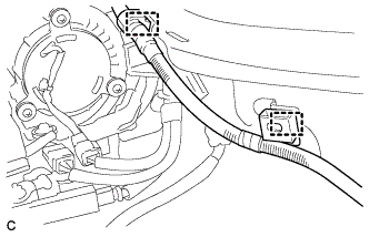 |
Disconnect the 2 wire harness clamps.
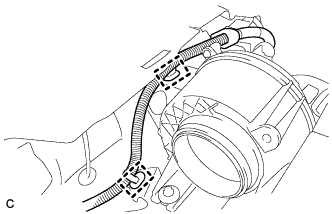 |
Disconnect the 2 wire harness clamps.
| 25. DISCONNECT HYBRID BATTERY JUNCTION BLOCK ASSEMBLY |
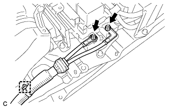 |
Remove the 2 nuts, then disconnect the frame wire from the hybrid battery junction block assembly.
Disconnect the clamp and frame wire.
| 26. REMOVE INVERTER RESERVE TANK ASSEMBLY |
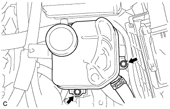 |
Remove the 2 bolts and separate the inverter reserve tank assembly.
| 27. REMOVE FRAME WIRE |
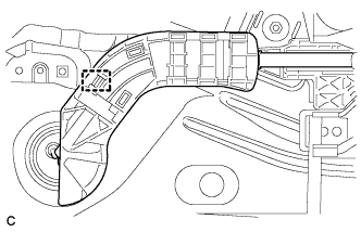 |
Remove the wire harness protector and disconnect the clamp from the floor panel.
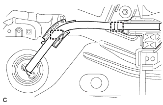 |
Disconnect the 2 wire harness clamps from the floor panel.
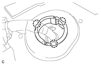 |
Disconnect the 3 claws and push the frame wire out from the floor panel.
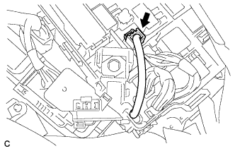 |
Disconnect the connector from the engine room junction block assembly.
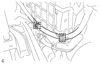 |
Disconnect the 2 clamps shown in the illustration.
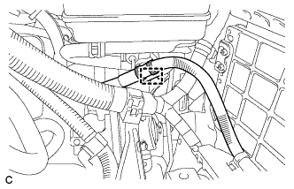 |
Disconnect the clamp shown in the illustration.
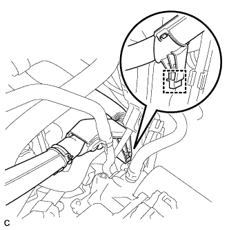 |
Disconnect the clamp shown in the illustration.
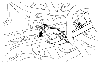 |
Remove the nut and separate the heater water pipe sub-assembly.
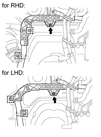 |
Remove the nut and 2 clamps shown in the illustration.
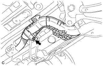 |
Remove the nut and clamp shown in the illustration.
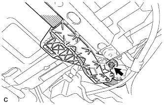 |
Remove the nut shown in the illustration.
Disconnect the 4 clamps and remove the frame wire.