DTC C1202/68 Master Reservoir Level Malfunction |
| DTC Code | INF Code | DTC Detection Condition | Trouble Area |
| C1202/68 | 371 | An open is detected in the switch signal circuit for 2 seconds or more. |
|
| ↑ | - | The reservoir level remains low. |
|
| 1.CHECK BRAKE FLUID LEVEL |
Check that the brake fluid level is sufficient.
Check for brake fluid leaks (Connection between the brake booster pump, brake master cylinder reservoir and brake booster with master cylinder, and the brake booster with master cylinder and wheel cylinders).
Check that the trouble code is not output again (Click here).
Check that there are no leaks from the connections between the brake booster pump and brake booster with master cylinder.
Bleed the air from the brake systems (Click here).
Connect the intelligent tester to the DLC3.
Turn the power switch on (IG).
Select the Data List on the intelligent tester (Click here).
| Tester Display | Measurement Item/Range | Normal Condition | Diagnostic Note |
| Accumulator Sensor | Accumulator pressure sensor / Min.: 0 V, Max.: 5 V | Specified value: 2.9 to 4.2 V | When brake fluid is stored in the accumulator: Accumulator pressure changes in accordance with volume of fluid stored in the accumulator |
Wait for 30 seconds without depressing the brake pedal.
Check that the accumulator pressure sensor output values change is within the specified range.
|
| ||||
| OK | |
 |
| 2.INSPECT BRAKE FLUID LEVEL WARNING SWITCH |
 |
Turn the power switch off.
Remove the reservoir filler cap and strainer.
Make sure that there is no looseness at the locking part and the connecting part of the connector.
Disconnect the brake fluid level warning switch connector.
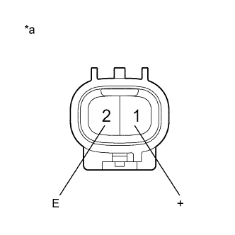
Measure the resistance according to the value(s) in the table below.
| Tester Connection | Switch Condition | Specified Condition |
| 1 (+) - 2 (E) | Brake fluid level warning switch OFF (Float up) | 1.84 to 2.16 kΩ |
| 1 (+) - 2 (E) | Brake fluid level warning switch ON (Float down) | Below 1 Ω |
| *a | Component without harness connected (Brake Fluid Level Warning Switch) |
| Result | Proceed to |
| OK | A |
| NG (for LHD) | B |
| NG (for RHD) | C |
|
| ||||
|
| ||||
| A | |
|
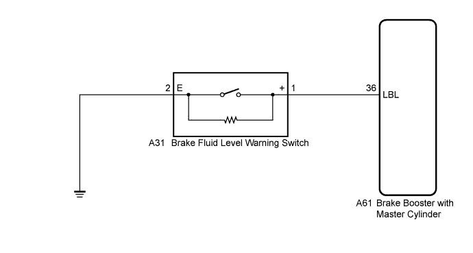
| 3.CHECK HARNESS AND CONNECTOR (SKID CONTROL ECU - BRAKE FLUID LEVEL WARNING SWITCH) |
Make sure that there is no looseness at the locking part and the connecting part of the connector.
Disconnect the skid control ECU connector.
Measure the resistance according to the value(s) in the table below.
| Tester Connection | Condition | Specified Condition |
| A61-36 (LBL) - A31-1 (+) | Always | Below 1 Ω |
| A61-36 (LBL) - Body ground | Always | 10 kΩ or higher |
| A31-2 (E) - Body ground | Always | Below 1 Ω |
|
| ||||
| OK | |
|
| 4.INSPECT SKID CONTROL ECU (SWITCH INPUT) |
 |
Reconnect the skid control ECU connector.
Turn the power switch on (IG).
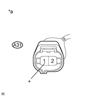
Measure the voltage according to the value(s) in the table below.
| Tester Connection | Switch Condition | Specified Condition |
| A31-1 (+) - Body ground | Power switch on (IG) | 4 to 7 V |
| *a | Front view of wire harness connector (to Brake Fluid Level Warning Switch) |
| Result | Proceed to |
| OK | A |
| NG (for LHD) | B |
| NG (for RHD) | C |
|
| ||||
|
| ||||
| A | |
|
| 5.CHECK BRAKE DISC |
Turn the power switch off.
Reconnect the brake fluid level warning switch connector.
Disconnect the brake pedal stroke sensor connector.
Perform a road test according to Freeze Frame Data or customer problem analysis. Check the brake line pressure vibration caused due to uneven wear of the disc according to brake pedal vibration.
|
| ||||
| OK | |
|
| 6.RECONFIRM DTC |
Reconnect the brake pedal stroke sensor connector.
Clear the DTCs (Click here).
Turn the power switch on (READY).
Perform a road test.
Check if the same DTC is recorded (Click here).
| Result | Proceed to |
| DTC (C1202/68) is not output | A |
| DTC (C1202/68) is output (for LHD) | B |
| DTC (C1202/68) is output (for RHD) | C |
|
| ||||
|
| ||||
| A | ||
 | ||
| ||

