LIGHTING SYSTEM > Low Beam Headlight Circuit |
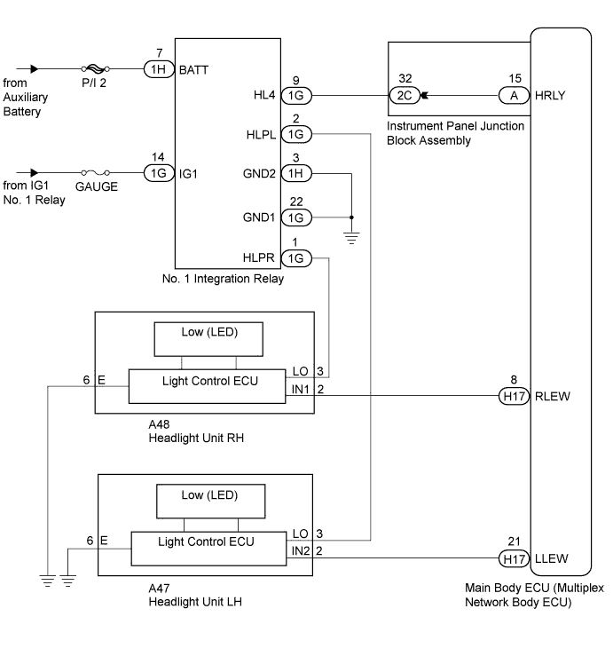
| for LED Headlight: |
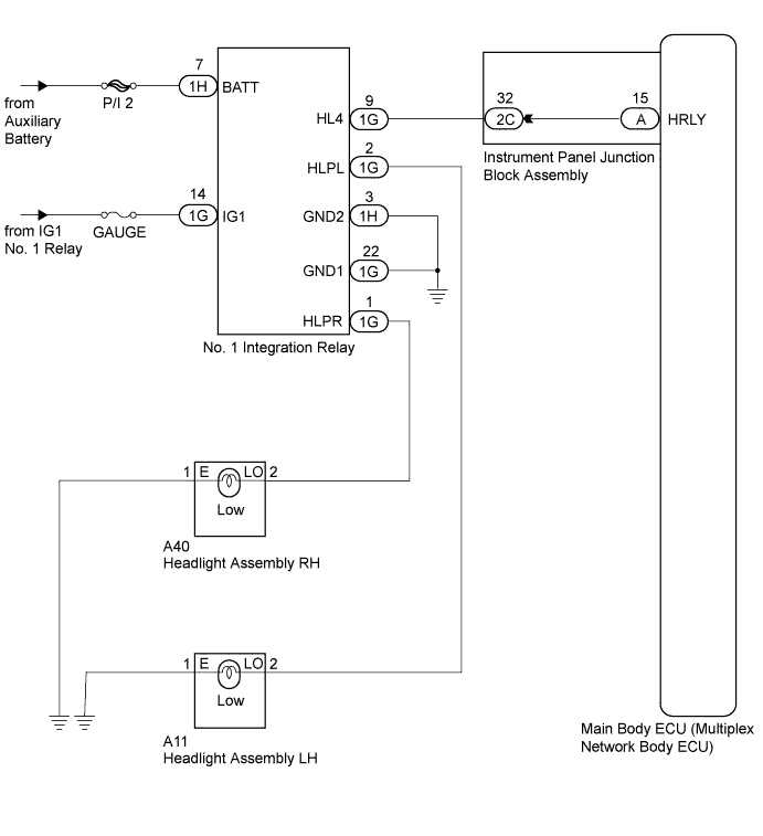
| except LED Headlight: |
| 1.PERFORM ACTIVE TEST USING INTELLIGENT TESTER |
Connect the intelligent tester to the DLC3.
Turn the power switch on (IG).
Turn the intelligent tester on.
Enter the following menus: Body / Main Body / Active Test.
Check that the relays operate.
| Tester Display | Test Part | Control Range | Diagnostic Note |
| Headlight Relay | Headlight relays | ON/OFF | - |
|
| ||||
| OK | ||
 | ||
| ||
| 2.CHECK HARNESS AND CONNECTOR (NO. 1 INTEGRATION RELAY - AUXILIARY BATTERY AND BODY GROUND) |
Disconnect the 1G and 1H No. 1 integration relay connectors.
Measure the voltage and resistance according to the value(s) in the table below.
| Tester Connector | Condition | Specified Condition |
| 1G-14 (IG1) - Body ground | Power switch on (IG) | 11 to 14 V |
| 1H-7 (BATT) - Body ground | Power switch off | 11 to 14 V |
| Tester Connection | Condition | Specified Condition |
| 1H-3 (GND2) - Body ground | Always | Below 1 Ω |
| 1G-22 (GND1) - Body ground | Always | Below 1 Ω |
|
| ||||
| OK | |
 |
| 3.CHECK HARNESS AND CONNECTOR (NO. 1 INTEGRATION RELAY - INSTRUMENT PANEL JUNCTION BLOCK) |
Disconnect the 1G No. 1 integration relay connector.
Disconnect the 2C instrument panel junction block assembly connector.
Measure the resistance according to the value(s) in the table below.
| Tester Connection | Condition | Specified Condition |
| 1G-9 (HL4) - 2C-32 | Always | Below 1 Ω |
| 1G-9 (HL4) - Body ground | Always | 10 kΩ or higher |
|
| ||||
| OK | |
|
| 4.INSPECT INSTRUMENT PANEL JUNCTION BLOCK ASSEMBLY |
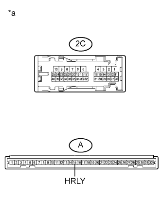 |
Remove the instrument panel junction block assembly.
Measure the resistance according to the value(s) in the table below.
| Tester Connection | Condition | Specified Condition |
| 2C-32 - A-15 (HRLY) | Always | Below 1 Ω |
| 2C-32 - Body ground | Always | 10 kΩ or higher |
| *a | Component without harness connected (Instrument Panel Junction Block Assembly) |
|
| ||||
| OK | |
|
| 5.REPLACE NO. 1 INTEGRATION RELAY |
Replace the combination meter assembly with a new or a known good one (Click here).
Check that the low beam headlights operate normally.
|
| ||||
| OK | ||
| ||
| ||


