DTC U0235 Lost Communication with Cruise Control Front Distance Range Sensor |
| DTC No. | DTC Detection Condition | Trouble Area |
| U0235 | When the power switch is on (IG), a communication error from the millimeter wave radar sensor to the driving support ECU is detected for approx. 1 second. |
|
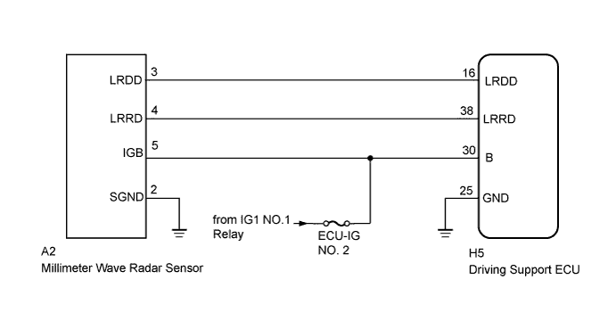
| 1.CHECK HARNESS AND CONNECTOR (DRIVING SUPPORT ECU - MILLIMETER WAVE RADAR SENSOR) |
Disconnect the driving support ECU and millimeter wave radar sensor connectors.
Measure the resistance according to the value(s) in the table below.
| Tester Connection | Condition | Specified Condition |
| H5-16 (LRDD) - A2-3 (LRDD) | Always | Below 1 Ω |
| A2-3 (LRDD) - Body ground | Always | 10 kΩ or higher |
| H5-16 (LRDD) - Body ground | Always | 10 kΩ or higher |
Reconnect the driving support ECU and millimeter wave radar sensor connectors.
|
| ||||
| OK | |
 |
| 2.CHECK MILLIMETER WAVE RADAR SENSOR (IGB VOLTAGE) |
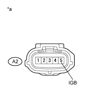 |
Disconnect the millimeter wave radar sensor connector.
Turn the power switch on (IG).
Measure the voltage according to the value(s) in the table below.
| Tester Connection | Switch Condition | Specified Condition |
| A2-5 (IGB) - Body ground | Power switch on (IG) | 11 to 14 V |
| *a | Front view of wire harness connector (to Millimeter Wave Radar Sensor) |
Reconnect the millimeter wave radar sensor connector.
|
| ||||
| OK | |
|
| 3.CHECK MILLIMETER WAVE RADAR SENSOR (SGND CIRCUIT) |
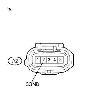 |
Disconnect the millimeter wave radar sensor connector.
Measure the resistance according to the value(s) in the table below.
| Tester Connection | Switch Condition | Specified Condition |
| A2-2 (SGND) - Body ground | Always | Below 1 Ω |
| *a | Front view of wire harness connector (to Millimeter Wave Radar Sensor) |
Reconnect the millimeter wave radar sensor connector.
|
| ||||
| OK | |
|
| 4.CHECK MILLIMETER WAVE RADAR SENSOR (LRDD OUTPUT VOLTAGE) |
Disconnect the driving support ECU connector.
Turn the power switch on (IG).
Measure the voltage according to the value(s) in the table below.
| Tester Connection | Switch Condition | Specified Condition |
| H5-16 (LRDD) - Body ground | Power switch on (IG) | 4.5 to 5.5 V |
Reconnect the driving support ECU connector.
|
| ||||
| OK | |
|
| 5.REPLACE DRIVING SUPPORT ECU |
Replace the driving support ECU (Click here).
| NEXT | |
|
| 6.CHECK DTC OUTPUT |
Clear the DTCs (Click here).
Turn the cruise control main switch on.
Drive the vehicle at the required speed (45 km/h (28 mph) or higher).
Check if the same DTC is output (Click here).
| Result | Proceed to |
| DTC U0235 is not output | A |
| DTC U0235 is output | B |
|
| ||||
| A | ||
 | ||
| ||

