DTC U0235 Lost Communication with Cruise Control Front Distance Range Sensor |
| DTC No. | DTC Detection Condition | Trouble Area |
| U0235 | The ECM detects a communication error signal (from the millimeter wave radar sensor assembly to the driving support ECU assembly) for 1 second or more while the dynamic radar cruise control is operating |
|
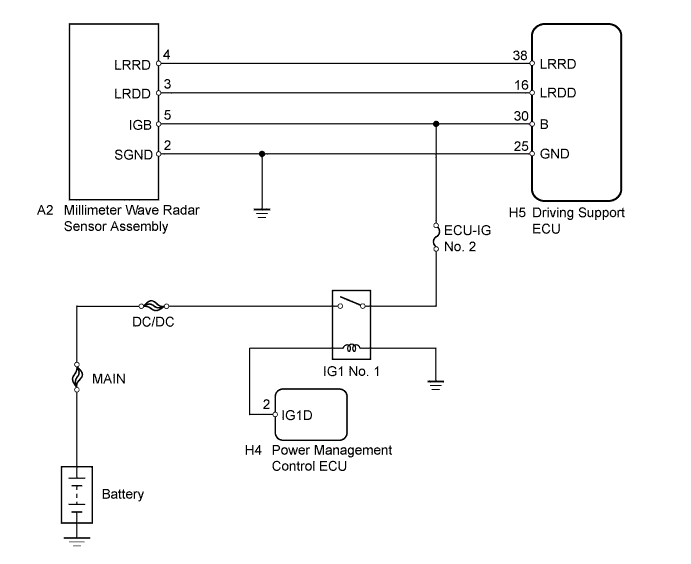
| 1.CHECK HARNESS AND CONNECTOR (MILLIMETER WAVE RADAR SENSOR ASSEMBLY POWER SOURCE) |
 |
Disconnect the millimeter wave radar sensor assembly connector.
Turn the power switch on (IG).
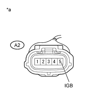
Measure the voltage according to the value(s) in the table below.
| Tester Connection | Switch Condition | Specified Condition |
| A2-5 (IGB) - Body ground | Power switch on (IG) | 11 to 14 V |
| *a | Front view of wire harness connector (to Millimeter Wave Radar Sensor Assembly) |
Reconnect the millimeter wave radar sensor assembly connector.
|
| ||||
| OK | |
 |
| 2.CHECK HARNESS AND CONNECTOR (DRIVING SUPPORT ECU - MILLIMETER WAVE RADAR SENSOR ASSEMBLY) |
Disconnect the driving support ECU assembly and millimeter wave radar sensor assembly connectors.
Measure the resistance according to the value(s) in the table below.
| Tester Connection | Condition | Specified Condition |
| H5-16 (LRDD) - A2-3 (LRDD) | Always | Below 1 Ω |
| Tester Connection | Condition | Specified Condition |
| H5-16 (LRDD) or A2-3 (LRDD) - Body ground | Always | 10 kΩ or higher |
Reconnect the driving support ECU assembly and millimeter wave radar sensor assembly connectors.
|
| ||||
| OK | |
|
| 3.CHECK HARNESS AND CONNECTOR (MILLIMETER WAVE RADAR SENSOR ASSEMBLY - BODY GROUND) |
 |
Disconnect the millimeter wave radar sensor assembly connector.
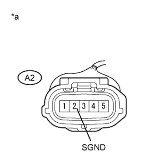
Measure the resistance according to the value(s) in the table below.
| Tester Connection | Condition | Specified Condition |
| A2-2 (SGND) - Body ground | Always | Below 1 Ω |
| *a | Front view of wire harness connector (to Millimeter Wave Radar Sensor Assembly) |
Reconnect the millimeter wave radar sensor assembly connector.
|
| ||||
| OK | |
|
| 4.CHECK MILLIMETER WAVE RADAR SENSOR ASSEMBLY |
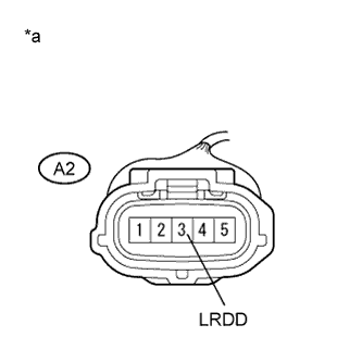 |
Measure the voltage according to the value(s) in the table below.
| Tester Connection | Condition | Specified Condition |
| A2-3 (LRDD) - Body ground | Power switch on (IG) | 4.5 to 5.5 V |
| *a | Front view of wire harness connector (to Millimeter Wave Radar Sensor Assembly) |
|
| ||||
| OK | ||
 | ||
| ||
| 5.REPLACE MILLIMETER WAVE RADAR SENSOR ASSEMBLY |
Replace the millimeter wave radar sensor assembly (Click here).
Adjust the millimeter wave radar sensor assembly (Click here).
| NEXT | |
|
| 6.CHECK WHETHER DTC OUTPUT RECURS (DTC U0235) |
Connect the intelligent tester to the DLC3.
Turn the power switch on (IG).
Clear the DTCs (Click here).
Perform the following to make sure that the DTC detection conditions are met.
Drive the vehicle at a speed of 50 km/h (30 mph) and 170 km/h (105 mph).
Turn the cruise control switch (ON-OFF button) on.
Push the -/SET switch to activate the cruise control.
Enter the following menus: Powertrain / Radar Cruise / DTC.
Read the DTCs.
| Result | Proceed to |
| DTC is not output | A |
| DTC U0235 is output | B |
|
| ||||
| A | ||
| ||
| ||


