DTC P3004-800 Power Cable Malfunction |
DTC P3004-801 Power Cable Malfunction |
| DTC No. | INF Code | DTC Detection Condition | Trouble Area |
| P3004 | 800 | Excessive overcurrent occurs during precharge (time from when SMRP turns on until when SMRG turns on). |
|
| P3004 | 801 | Minimal overcurrent occurs during precharge (time from when SMRP turns on until when SMRG turns on). |
| 1.CHECK DTC OUTPUT (HYBRID CONTROL) |
Connect the intelligent tester to the DLC3.
Turn the power switch on (IG).
Enter the following menus: Powertrain / Hybrid Control / DTC.
Check if DTCs are output.
| Result | Proceed to |
| P3004-800 or P3004-801 only is output. | A |
| DTCs shown in Table 1 are output simultaneously. | B |
| DTCs shown in Table 2 are output simultaneously. | C |
| DTC No. | Relevant Diagnosis |
| P0A09-265 | DC/DC Converter Status Circuit Low Input |
| P0A10-263 | DC/DC Converter Status Circuit High Input |
| DTC No. | Relevant Diagnosis |
| P0ABF-123 | Hybrid Battery Pack Current Sensor Circuit |
| P0AC0-123 | Hybrid Battery Pack Current Sensor Circuit Range / Performance |
| P0AC1-123 | Hybrid Battery Pack Current Sensor Circuit Low |
| P0AC2-123 | Hybrid Battery Pack Current Sensor Circuit High |
| P0AFC-123 | Hybrid Battery Pack Sensor Module |
| P0B3D-123 | Hybrid Battery Voltage Sensor "A" Circuit Low |
| P0B42-123 | Hybrid Battery Voltage Sensor "B" Circuit Low |
| P0B47-123 | Hybrid Battery Voltage Sensor "C" Circuit Low |
| P0B4C-123 | Hybrid Battery Voltage Sensor "D" Circuit Low |
| P0B51-123 | Hybrid Battery Voltage Sensor "E" Circuit Low |
| P0B56-123 | Hybrid Battery Voltage Sensor "F" Circuit Low |
| P0B5B-123 | Hybrid Battery Voltage Sensor "G" Circuit Low |
| P0B60-123 | Hybrid Battery Voltage Sensor "H" Circuit Low |
| P0B65-123 | Hybrid Battery Voltage Sensor "I" Circuit Low |
| P0B6A-123 | Hybrid Battery Voltage Sensor "J" Circuit Low |
| P0B6F-123 | Hybrid Battery Voltage Sensor "K" Circuit Low |
| P0B74-123 | Hybrid Battery Voltage Sensor "L" Circuit Low |
| P0B79-123 | Hybrid Battery Voltage Sensor "M" Circuit Low |
| P0B7E-123 | Hybrid Battery Voltage Sensor "N" Circuit Low |
| P0B83-123 | Hybrid Battery Voltage Sensor "O" Circuit Low |
| P308A-123 | Hybrid Battery Voltage Detection Circuit Open |
| U029A-123 | Lost Communication with Hybrid Battery Pack Sensor Module |
Turn the power switch off.
|
| ||||
|
| ||||
| A | |
 |
| 2.CHECK CONNECTOR CONNECTION CONDITION (POWER MANAGEMENT CONTROL ECU CONNECTOR) |
Check the connections of the power management control ECU connectors.
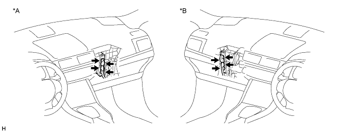
| *A | for LHD | *B | for RHD |
|
| ||||
| OK | |
|
| 3.CHECK COMPRESSOR WITH MOTOR ASSEMBLY |
Check that the service plug grip is not installed.
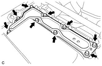 |
Remove the inverter cover from the inverter with converter assembly.
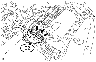 |
Disconnect the No. 2 engine wire (air conditioning harness) E2 from the inverter with converter assembly.
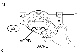 |
Measure the resistance according to the value(s) in the table below.
| Tester Connection (Tester Probe Polarity) | Switch Condition | Specified Condition |
| E2-1 (ACPB) - E2-2 (ACPE) | Power switch off | 100 kΩ or higher |
| *1 | Shielded Wire Ground |
| *a | Front view of No. 2 Engine Wire (Air Conditioning Harness) connector (to Inverter with Converter Assembly) |
Connect the No. 2 engine wire (air conditioning harness) from the inverter with converter assembly.
Install the inverter cover to the inverter with converter assembly.
|
| ||||
| OK | |
|
| 4.CHECK HARNESS AND CONNECTOR (RESISTANCE VALUE OF NODD INSIDE POWER MANAGEMENT CONTROL ECU) |
Disconnect connector A62 from the inverter with converter assembly.
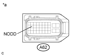 |
Measure the resistance according to the value(s) in the table below.
| Tester Connection | Switch Condition | Specified Condition |
| A62-12 (NODD) - Body ground | Power switch off | 120 to 140 kΩ |
| *a | Front view of wire harness connector (to Inverter With Converter Assembly) |
Connect the inverter with converter assembly connector.
|
| ||||
| OK | |
|
| 5.CHECK FRAME WIRE |
Check that the service plug grip is not installed.
|
Remove the inverter cover from the inverter with converter assembly.
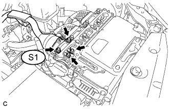 |
Disconnect the frame wire (high voltage DC connector) S1 from the inverter with converter assembly.
Remove the upper hybrid battery cover sub-assembly (Click here).
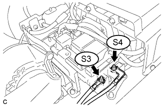 |
Measure the resistance according to the value(s) in the table below.
| Tester Connection | Switch Condition | Specified Condition |
| S3-1 (CEI) - S4-1 (CBI) | Power switch off | 10 kΩ or higher |
Install the upper hybrid battery cover sub-assembly (Click here).
Connect the frame wire (high voltage DC connector) to inverter with converter assembly.
Install the inverter cover to the inverter with converter assembly.
|
| ||||
| OK | ||
 | ||
| ||
| 6.CHECK HARNESS AND CONNECTOR (POWER MANAGEMENT CONTROL ECU - INVERTER WITH CONVERTER) |
Disconnect connector A62 from the inverter with converter assembly.
Disconnect connector A19 from power management control ECU.
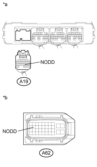 |
Measure the resistance according to the value(s) in the table below.
| Tester Connection | Switch Condition | Specified Condition |
| A19-21 (NODD) - A62-12 (NODD) | Power switch off | Below 1 Ω |
| Tester Connection | Switch Condition | Specified Condition |
| A19-21 (NODD) or A62-12 (NODD) - Body ground and other terminals | Power switch off | 10 kΩ or higher |
| *a | Rear view of wire harness connector (to Power Management Control ECU) |
| *b | Front view of wire harness connector (to Inverter with Converter Assembly) |
Connect the power management control ECU connector.
Connect the inverter with converter assembly connector.
|
| ||||
| OK | ||
| ||
| ||
| 7.CHECK NO. 2 ENGINE WIRE |
Check that the service plug grip is not installed.
|
Remove the inverter cover from the inverter with converter assembly.
|
Disconnect the No. 2 engine wire (air conditioning harness) E2 from the inverter with converter assembly.
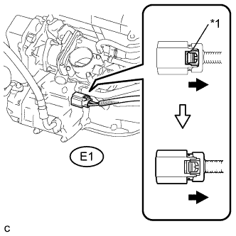 |
Disconnect the No. 2 engine wire (air conditioning harness) E1 from the compressor with motor assembly.
| *1 | Green Lock |
|
Measure the resistance according to the value(s) in the table below.
| Tester Connection | Switch Condition | Specified Condition |
| E2-1 (ACPB) - E2-2 (ACPE) | Power switch off | 10 kΩ or higher |
| *1 | Shielded Wire Ground |
| *a | Front view of No. 2 Engine Wire (Air Conditioning Harness) connector (to Inverter with Converter Assembly) |
Connect the No. 2 engine wire (air conditioning harness) to the compressor with motor assembly.
Connect the No. 2 engine wire (air conditioning harness) from the inverter with converter assembly.
Install the inverter cover to the inverter with converter assembly.
|
| ||||
| OK | ||
| ||
| ||
| 8.CHECK HYBRID BATTERY JUNCTION BLOCK ASSEMBLY |
Check that the service plug grip is not installed.
Remove the upper hybrid battery cover sub-assembly (Click here).
|
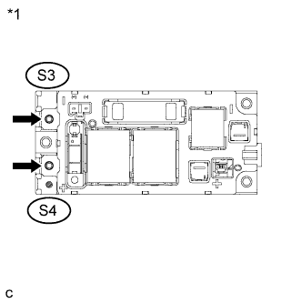
Disconnect the frame wire S3 and S4 from the hybrid battery junction block assembly.
 |
Measure the resistance according to the value(s) in the table below.
| Tester Connection | Switch Condition | Specified Condition |
| S3-1 (CEI) - S4-1 (CBI) | Power switch off | 10 kΩ or higher |
| *1 | Hybrid Battery Junction Block Assembly |
Connect the frame wire to the hybrid battery junction block assembly.
Install the upper hybrid battery cover sub-assembly (Click here).
|
| ||||
| OK | ||
| ||
| ||


