DTC P0571 Brake Switch "A" Circuit |
| DTC No. | DTC Detection Condition | Trouble Area |
| P0571 | Voltage of STP signal and that of ST1- signal of power management control ECU are less than 1 V for 0.5 seconds or more |
|
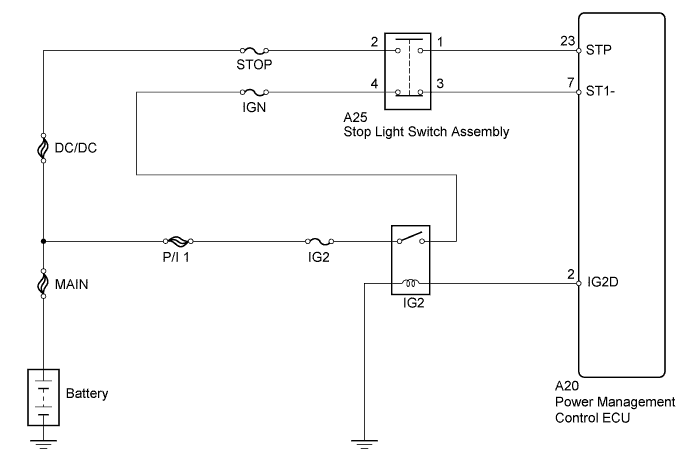
| 1.INSPECT STOP LIGHT SWITCH ASSEMBLY (POWER SOURCE) |
 |
Disconnect the stop light switch assembly connector.
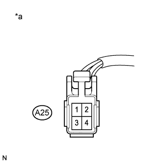
Measure the voltage according to the value(s) in the table below.
| Tester Connection | Condition | Specified Condition |
| A25-2 - Body ground | Always | 11 to 14 V |
| *a | Front view of wire harness connector (to Stop Light Switch Assembly) |
Reconnect the stop light switch assembly connector.
|
| ||||
| OK | |
 |
| 2.INSPECT STOP LIGHT SWITCH ASSEMBLY (POWER SOURCE) |
|
Disconnect the stop light switch assembly connector.
Turn the power switch on (IG).
Measure the voltage according to the value(s) in the table below.
| Tester Connection | Switch Condition | Specified Condition |
| A25-4 - Body ground | Power switch on (IG) | 11 to 14 V |
| *a | Front view of wire harness connector (to Stop Light Switch Assembly) |
Reconnect the stop light switch assembly connector.
|
| ||||
| OK | |
|
| 3.INSPECT STOP LIGHT SWITCH ASSEMBLY |
 |
Remove the stop light switch assembly (Click here).
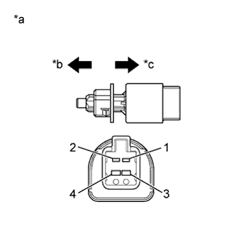
Measure the resistance according to the value(s) in the table below.
| Tester Connection | Switch Condition | Specified Condition |
| 1 - 2 | Switch pin not pushed | Below 1 Ω |
| 3 - 4 | Switch pin not pushed | 10 kΩ or higher |
| 1 - 2 | Switch pin pushed | 10 kΩ or higher |
| 3 - 4 | Switch pin pushed | Below 1 Ω |
| *a | Component without harness connected (Stop Light Switch Assembly) |
| *b | Not pushed |
| *c | Pushed |
Reinstall the stop light switch assembly (Click here).
|
| ||||
| OK | |
|
| 4.CHECK HARNESS AND CONNECTOR (POWER MANAGEMENT CONTROL ECU - STOP LIGHT SWITCH ASSEMBLY) |
Disconnect the power management control ECU connector.
Disconnect the stop light switch assembly connector.
Measure the resistance according to the value(s) in the table below.
| Tester Connection | Condition | Specified Condition |
| A20-23 (STP) - A25-1 | Always | Below 1 Ω |
| A20-7 (ST1-) - A25-3 | Always | Below 1 Ω |
| Tester Connection | Condition | Specified Condition |
| A20-23 (STP) or A25-1 - Body ground | Always | 10 kΩ or higher |
| A20-7 (ST1-) or A25-3 - Body ground | Always | 10 kΩ or higher |
Reconnect the stop light switch assembly connector.
Reconnect the power management control ECU connector.
|
| ||||
| OK | ||
 | ||
| ||

