THEFT DETERRENT SYSTEM > ECU Power Source Circuit |
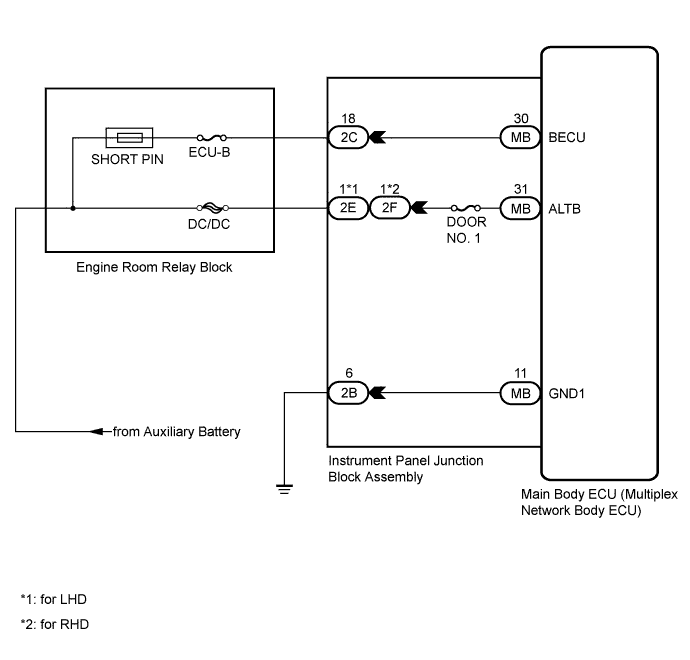
| 1.INSPECT INSTRUMENT PANEL JUNCTION BLOCK ASSEMBLY |
Disconnect the 2E*1, 2F*2, 2B and 2C instrument panel junction block assembly and MB main body ECU (multiplex network body ECU) connectors.
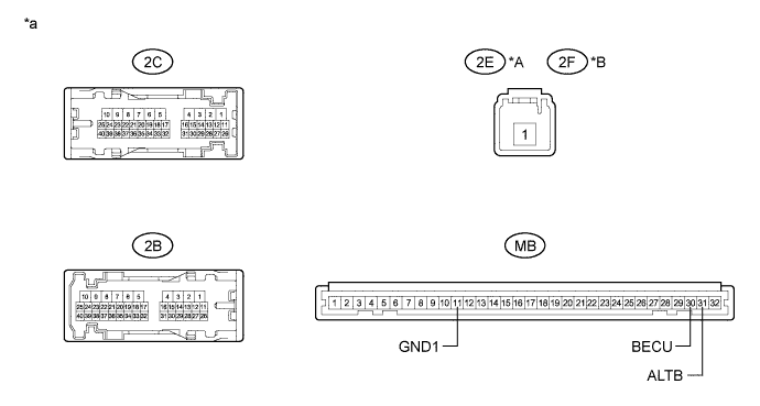
Measure the resistance according to the value(s) in the table below.
| Tester Connection | Condition | Specified Condition |
| 2B-6 - MB-11 (GND1) | Always | Below 1 Ω |
| 2B-6 - Body ground | Always | 10 kΩ or higher |
| 2C-18 - MB-30 (BECU) | Always | Below 1 Ω |
| 2C-18 - Body ground | Always | 10 kΩ or higher |
| 2E-1*1 - MB-31 (ALTB) 2F-1*2 - MB-31 (ALTB) | Always | Below 1 Ω |
| 2E-1*1 - Body ground 2F-1*2 - Body ground | Always | 10 kΩ or higher |
| *A | for LHD | *B | for RHD |
| *a | Component without harness connected (Instrument Panel Junction Block Assembly) | - | - |
|
| ||||
| OK | |
 |
| 2.CHECK HARNESS AND CONNECTOR (INSTRUMENT PANEL JUNCTION BLOCK ASSEMBLY - AUXILIARY BATTERY) |
Measure the voltage according to the value(s) in the table below.
| Tester Connection | Condition | Specified Condition |
| 2E-1*1 - Body ground 2F-1*2 - Body ground | Power switch off | 11 to 14 V |
| 2C-18 - Body ground | Power switch off | 11 to 14 V |
|
| ||||
| OK | |
|
| 3.CHECK HARNESS AND CONNECTOR (INSTRUMENT PANEL JUNCTION BLOCK ASSEMBLY - BODY GROUND) |
Measure the resistance according to the value(s) in the table below.
| Tester Connection | Condition | Specified Condition |
| 2B-6 - Body ground | Always | Below 1 Ω |
|
| ||||
| OK | ||
 | ||
| ||

