NAVIGATION SYSTEM (for DVD) > TERMINALS OF ECU |
| DISPLAY AND NAVIGATION MODULE DISPLAY |
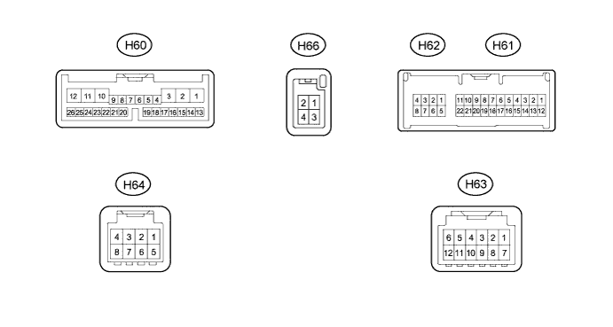
| Terminal No. (Symbol) | Wiring Color | Terminal Description | Condition | Specified Condition |
| H60-1 (+B1) - H60-10 (GND1) | V - W-B | Power source | Power switch off | 11 to 14 V |
| H60-2 (ACC) - H60-10 (GND1) | B - W-B | Accessory (ON) | Power switch on (ACC) | 11 to 14 V |
| Power switch off | Below 1 V | |||
| H60-3 (IG) - H60-10 (GND1) | V - W-B | Power source (IG) | Power switch on (IG) | 11 to 14 V |
| Power switch off | Below 1 V | |||
| H60-4 (MACC) - H60-10 (GND1) | B - W-B | Telephone microphone assembly power supply | Power switch off → on (ACC) | Below 1 V → 4 to 6 V |
| H60-5 (MIN+) - H60-10 (GND1) | W - W-B | Microphone voice signal | See "Microphone & Voice Recognition Check" in Operation Check (Click here) | - |
| H60-6 (MIN-) - Body ground | R - Body ground | Microphone voice signal | See "Microphone & Voice Recognition Check" in Operation Check (Click here) | - |
| H60-7 (SGND) - H60-10 (GND1) | Shield - W-B | Shield ground | Always | Below 1 V |
| H60-10 (GND1) - Body ground | W-B - Body ground | Ground | Always | Below 1 V |
| H60-11 (ILL-) - H60-10 (GND1) | B - W-B | Illumination signal | Power switch on (IG) Light control switch off → tail or head position (Light intensity not max. or min.) | Below 1 V → Pulse generation |
| H60-12 (ILL+) - H60-10 (GND1) | G - W-B | Illumination signal | Power switch on (IG) Light control switch off → tail or head position | Below 1 V → 11 to 14 V |
| H60-13 (TX2+) | G | AVC-LAN communication signal | - | - |
| H60-14 (TX2-) | P | AVC-LAN communication signal | - | - |
| H60-17 (PKB) - H60-10 (GND1) | R - W-B | Parking brake signal | See "Vehicle Signal Check Mode" in Operation Check (Click here) | - |
| H60-18 (SPD) - H60-10 (GND1) | V - W-B | Vehicle speed signal from combination meter assembly | See "Vehicle Signal Check Mode" in Operation Check (Click here) | - |
| H60-20 (SNS2) - H60-10 (GND1) | V - W-B | Microphone connection detection signal | Always | Below 1 V |
| H60-21 (CANH) | R | CAN communication signal | - | - |
| H60-22 (CANL) | W | CAN communication signal | - | - |
| H60-23 (SWG) - Body ground | W - Body ground | Steering pad switch signal | Always | Below 1 V |
| H60-24 (SW2) - H60-23 (SWG) | G - W | Steering pad switch signal | No switch pushed → MODE switch pushed → On hook switch pushed → Off hook switch pushed → Voice switch pushed | 4.44 to 5.43 V → 0.45 to 0.65 V → 1.19 to 1.49 V → 2.09 to 2.54 V → 3.2 to 3.88 V |
| H60-25 (SW1) - H60-23 (SWG) | GR - W | Steering pad switch signal | No switch pushed → Seek+ switch pushed → Seek- switch pushed → Volume+ switch pushed → Volume- switch pushed | 4.44 to 5.43 V → 0.45 to 0.65 V → 1.19 to 1.49 V → 2.09 to 2.54 V → 3.2 to 3.88 V |
| H61-1 (TX1+) | R | AVC-LAN communication signal | - | - |
| H61-2 (TX1-) | L | AVC-LAN communication signal | - | - |
| H61-9 (VV+) - H60-10 (GND1)*1 | R - W-B | Display signal | DVD playing on multi-display | A waveform synchronized with display signals is output. (Refer to waveform 1) |
| H61-10 (NTSF) - H60-10 (GND1)*1 | G - W-B | Display signal | DVD playing on multi-display | A waveform synchronized with display signals is output. (Refer to waveform 2) |
| H61-11 (VMTF) - H60-10 (GND1) | GR - W-B | Visual mute signal | When image on display switches | 3.5 V or higher → Below 1 V → 3.5 V or higher |
| H61-12 (TX3+) | R | AVC-LAN communication signal | - | - |
| H61-13 (TX3-) | L | AVC-LAN communication signal | - | - |
| H61-20 (VV-) - Body ground*1 | G - Body ground | Ground | Always | Below 1 V |
| H61-21 (SGD1) - H60-10 (GND1)*1 | R - W-B | Ground | Always | Below 1 V |
| H61-22 (SLD1) - H60-10 (GND1)*1 | Shield - W-B | Shield ground | Always | Below 1 V |
| H62-1 (MI+) | B | MOST communication signal | - | - |
| H62-2 (SLDI) - H60-10 (GND1) | W-B - W-B | Shield ground | Always | Below 1 V |
| H62-3 (MO+) | B | MOST communication signal | - | - |
| H62-5 (MI-) | W | MOST communication signal | - | - |
| H62-6 (SLDO) - H60-10 (GND1) | W-B - W-B | Shield ground | Always | Below 1 V |
| H62-7 (MO-) | W | MOST communication signal | - | - |
| H62-8 (WUO) - H60-10 (GND1) | R - W-B | MOST communication signal | Power switch on (ACC) | 4.5 V or higher |
| Power switch off | Below 1 V | |||
| H64-1 (AGND) - Body ground | Shield - Body ground | Shield ground | Always | Below 1 V |
| H64-3 (VAR+) - H64-7 (VA-) | W - B | Sound signal (Right) | USB audio device playing (When stereo jack adapter used) | A waveform synchronized with sounds is output. |
| H64-4 (VAL+) - H64-7 (VA-) | R - B | Sound signal (Left) | USB audio device playing (When stereo jack adapter used) | A waveform synchronized with sounds is output. |
| H64-7 (VA-) - H60-10 (GND1) | B - W-B | Sound signal ground | Always | Below 1 V |
| H63-7 (GND) - H60-10 (GND1) | L - W-B | Ground | Always | Below 1 V |
| H63-9 (TX+) | W | AVC-LAN communication signal | - | - |
| H63-10 (TX-) | V | AVC-LAN communication signal | - | - |
| H63-11 (ACC) - H60-10 (GND1) | R - W-B | Accessory (ON) | Power switch on (ACC) | 11 to 14 V |
| Power switch off | Below 1 V | |||
| H63-12 (+B) - H60-10 (GND1) | B - W-B | Power source | Power switch off | 11 to 14 V |
| H66-1 (+B) - H66-4 (G) | B - L | Power source | Power switch off | 11 to 14 V |
| H66-2 (ACC) - H66-4 (G) | R - L | Accessory (ON) | Power switch on (ACC) | 11 to 14 V |
| Power switch off | Below 1 V | |||
| H66-4 (G) - Body ground | L - Body ground | Ground | Always | Below 1 V |
Reference (Oscilloscope waveform):
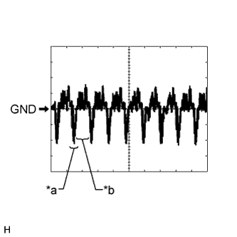 |
Waveform 1
| Item | Content |
| Measurement Terminal | H61-9 (VV+) - H60-10 (GND1) |
| Measurement Setting | 200 mV/DIV., 50 μs/DIV. |
| Condition | DVD is playing on multi-display |
|
Waveform 2
| Item | Content |
| Measurement Terminal | H61-10 (NTSF) - H60-10 (GND1) |
| Measurement Setting | 200 mV/DIV., 50 μs/DIV. |
| Condition | DVD is playing on multi-display |
| *a | Synchronization Signal |
| *b | Video Waveform |
| CENTER INSTRUMENT CLUSTER FINISH PANEL ASSEMBLY (MULTI-DISPLAY) |

| Terminal No. (Symbol) | Wiring Color | Terminal Description | Condition | Specified Condition |
| H20-2 (NTS1) - H20-6 (GND1) | G - W-B | Display signal | DVD playing on multi-display | A waveform synchronized with display signals is output. (Refer to waveform 3) |
| H20-3 (MTX+) | V | AVC-LAN communication signal | - | - |
| H20-4 (ILL) - H20-6 (GND1) | G - W-B | Illumination signal | Power switch on (IG) Light control switch off → tail or head position | Below 1 V → 11 to 14 V |
| H20-5 (+B) - H20-6 (GND1) | P - W-B | Power source | Power switch off | 11 to 14 V |
| H20-6 (GND1) - Body ground | W-B - Body ground | Ground | Always | Below 1 V |
| H20-7 (SGN1) - H20-6 (GND1) | R - W-B | Ground | Always | Below 1 V |
| H20-8 (MTX-) | P | AVC-LAN communication signal | - | - |
| H20-9 (VMT1) - H20-6 (GND1) | GR - W-B | Visual mute signal | When image on display switches | 3.5 V or higher → Below 1 V → 3.5 V or higher |
| H20-10 (ACC) - H20-6 (GND1) | R - W-B | Accessory (ON) | Power switch on (ACC) | 11 to 14 V |
| Power switch off | Below 1 V |
Reference (Oscilloscope waveform):
|
Waveform 3
| Item | Content |
| Measurement Terminal | H20-2 (NTS1) - H20-6 (GND1) |
| Measurement Setting | 200 mV/DIV., 50 μs/DIV. |
| Condition | DVD is playing on multi-display |
| *a | Synchronization Signal |
| *b | Video Waveform |
| MULTI-DISPLAY |

| Terminal No. (Symbol) | Wiring Color | Terminal Description | Condition | Specified Condition |
| DC1-2 (ILL) - DC1-13 (GND1) | - | Illumination signal | Power switch on (IG) Light control switch off → tail or head position | Below 1 V → 11 to 14 V |
| DC1-4 (NTS1) - DC1-13 (GND1) | - | Display signal | DVD playing on multi-display | A waveform synchronized with display signals is output. (Refer to waveform 4) |
| DC1-7 (MTX+) | - | AVC-LAN communication signal | - | - |
| DC1-11 (VMT1) - DC1-13 (GND1) | - | Visual mute signal | When image on display switches | 3.5 V or higher → Below 1 V → 3.5 V or higher |
| DC1-12 (+B) - DC1-13 (GND1) | - | Power source | Power switch off | 11 to 14 V |
| DC1-13 (GND1) - Body ground | - | Ground | Always | Below 1 V |
| DC1-16 (SGN1) - DC1-13 (GND1) | - | Ground | Always | Below 1 V |
| DC1-19 (MTX-) | - | AVC-LAN communication signal | - | - |
| DC1-24 (ACC) - DC1-13 (GND1) | - | Accessory (ON) | Power switch on (ACC) | 11 to 14 V |
| Power switch off | Below 1 V |
Reference (Oscilloscope waveform):
|
Waveform 4
| Item | Content |
| Measurement Terminal | DC1-4 (NTS1) - DC1-13 (GND1) |
| Measurement Setting | 200 mV/DIV., 50 μs/DIV. |
| Condition | DVD is playing on multi-display |
| *a | Synchronization Signal |
| *b | Video Waveform |
| DISPLAY MODULE BOARD |

| Terminal No. (Symbol) | Wiring Color | Terminal Description | Condition | Specified Condition |
| H21-1 (+B2) - H21-3 (SGND) | G - W-B | Power source | Power switch off | 11 to 14 V |
| H21-2 (ACC2) - H21-3 (SGND) | B - W-B | Accessory (ON) | Power switch on (ACC) | 11 to 14 V |
| Power switch off | Below 1 V | |||
| H21-3 (SGND) - Body ground | W-B - Body ground | Ground | Always | Below 1 V |
| H21-9 (TX4+) | G | AVC-LAN communication signal | - | - |
| H21-10 (TX4-) | P | AVC-LAN communication signal | - | - |
| H21-11 (TX5+) | V | AVC-LAN communication signal | - | - |
| H21-12 (TX5-) | P | AVC-LAN communication signal | - | - |
| H21-13 (VCC) - H21-3 (SGND) | G - W-B | Multi-display open/close switch signal | Power switch on (IG) Multi-display open/close switch off → on | 4.9 V or higher → Below 1.5 V |
| H21-14 (VDD) - H21-3 (SGND) | L - W-B | Multi-display tilt switch signal | Power switch on (IG) Multi-display tilt switch off → on | 4.9 V or higher → Below 1.5 V |
| REMOTE TOUCH |
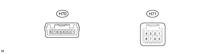
| Terminal No. (Symbol) | Wiring Color | Terminal Description | Condition | Specified Condition |
| H70-1 (GND) - Body ground | W-B - Body ground | Ground | Always | Below 1 V |
| H70-4 (ILL-) - H70-1 (GND) | BR - W-B | Illumination signal | Power switch on (IG) Light control switch off → tail or head position (Light intensity is not max. or min.) | Below 1 V → Pulse generation |
| H70-6 (ILL+) - H70-1 (GND) | G - W-B | Illumination signal | Power switch on (IG) Light control switch off → tail or head position | Below 1 V → 11 to 14 V |
| H70-7 (ACC) - H70-1 (GND) | R - W-B | Accessory (ON) | Power switch on (ACC) | 11 to 14 V |
| Power switch off | Below 1 V | |||
| H70-8 (+B) - H70-1 (GND) | R - W-B | Power source | Power switch off | 11 to 14 V |
| H71-1 (MO+) | B | MOST communication signal | - | - |
| H71-2 (MO-) | W | MOST communication signal | - | - |
| H71-3 (SLDO) - H70-1 (GND) | W-B - W-B | Shield ground | Always | Below 1 V |
| H71-5 (MI-) | W | MOST communication signal | - | - |
| H71-6 (MI+) | B | MOST communication signal | - | - |
| H71-7 (SLDI) - H70-1 (GND) | W-B - W-B | Shield ground | Always | Below 1 V |
| H71-8 (WUI) - H70-1 (GND) | R - W-B | MOST communication signal | Power switch on (ACC) | 4.5 V or higher |
| Power switch off | Below 1 V |
| NAVIGATION MODULE BOARD |

| Terminal No. (Symbol) | Wiring Color | Terminal Description | Condition | Specified Condition |
| H65-1 (+B) - H65-5 (G) | B - L | Power source | Power switch off | 11 to 14 V |
| H65-3 (ACC) - H65-5 (G) | R - L | Power source (ACC) | Power switch off | Below 1 V |
| Power switch on (ACC) | 11 to 14 V | |||
| H65-5 (G) - Body Ground | L - Body Ground | Ground | Always | Below 1 V |
| RADIO RECEIVER ASSEMBLY (Click here) |
| STEREO COMPONENT AMPLIFIER ASSEMBLY (Click here) |
| PARKING ASSIST ECU (Click here) |
| MULTI-MEDIA INTERFACE ECU ASSEMBLY (Click here) |
| CENTER CLUSTER MODULE CIRCUIT (Click here) |
