NAVIGATION SYSTEM (for DVD) > SYSTEM DESCRIPTION |
| NAVIGATION SYSTEM OUTLINE |
Vehicle position tracking methods
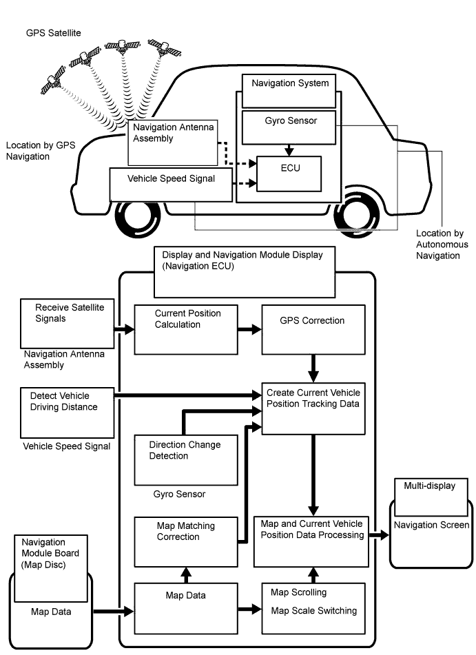
It is essential that the navigation system correctly tracks the current vehicle position and displays it on the map. There are 2 methods to track the current vehicle position: autonomous (dead reckoning) and GPS* (satellite) navigation. Both navigation methods are used in conjunction with each other.
*: GPS (Global Positioning System)
| Operation | Description |
| Vehicle Position Calculation | The display and navigation module display calculates the current vehicle position (direction and current position) using the direction deviation signal from the gyro sensor and driving distance signal from the vehicle speed sensor and creates the driving route. |
| Map Display Processing | The display and navigation module display processes the vehicle position data, vehicle driving track and map data from the map disc. |
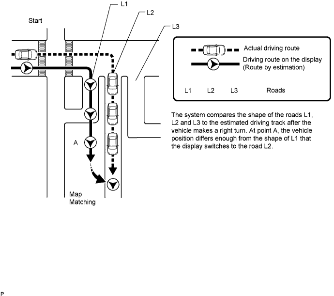
| Map Matching | The map data from the map disc is compared to the vehicle position and driving track data. Then, the vehicle position is matched with the nearest road. |
| GPS Correction | The vehicle position is matched to the position measured by the GPS. Then, the GPS measurement position data is compared with the vehicle position and driving track data. If the position is very different, the GPS measurement position is used. |
| Distance Correction | The vehicle speed signal includes error caused by tire wear and slippage between the tires and road surface. Distance correction is performed to account for this. The display and navigation module display automatically offsets the signal to make up for the difference between the distance signal and distance data of the map. The offset is automatically updated. |
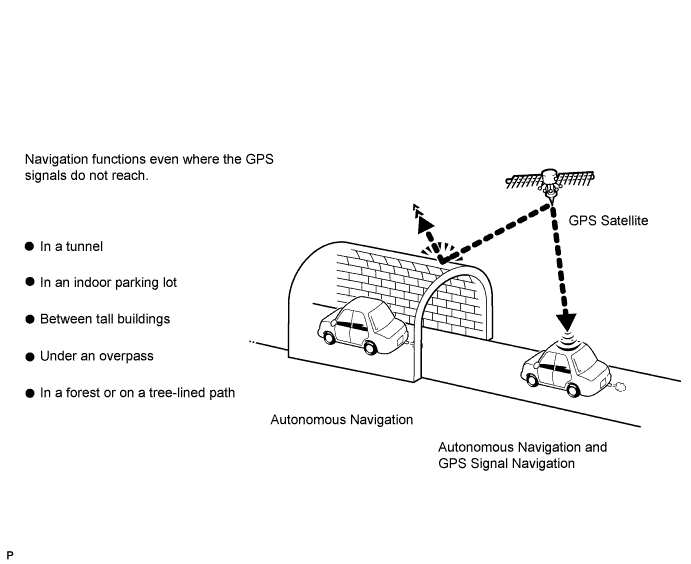
Autonomous navigation
This method determines the relative vehicle position based on the driving track determined by the gyro located in the display and navigation module display and the vehicle speed signal.
Gyro sensor
Used to calculate the direction by detecting angular velocity. It is located in the display and navigation module display.
Vehicle speed signal
Used to calculate the vehicle driving distance.
GPS* navigation (Satellite navigation)
This method detects the absolute vehicle position using radio waves from GPS satellites.
*: GPS satellites were launched by the U.S. Department of Defense for military purposes.
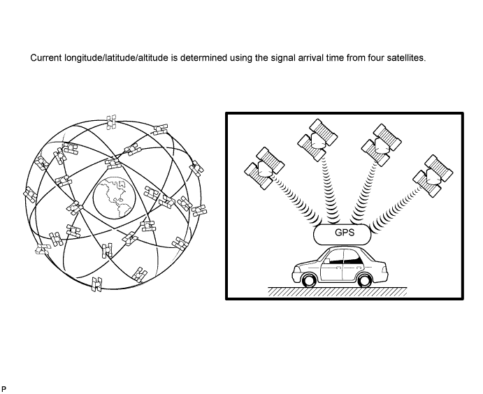
| Number of Satellites | Measurement | Description |
| 2 or less | Measurement is impossible | Vehicle position cannot be obtained because the number of satellites is not enough. |
| 3 | 2-dimensional measurement is possible | Vehicle position is obtained based on the current longitude and latitude. (This is less precise than 3-dimensional measurement.) |
| 4 | 3-dimensional measurement is possible | Vehicle position is obtained based on the current longitude, latitude and altitude. |
Map matching
The current driving route is calculated by autonomous navigation (according to the gyro sensor and vehicle speed signal) and GPS navigation. This information is then compared with possible road shapes from the map data in the map disc and the vehicle position is set onto the most appropriate road.
| MULTI-DISPLAY OUTLINE |
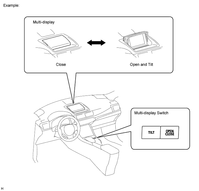
A pop-up type multi-display is built into the center instrument cluster finish panel assembly. Opening, closing and tilt angle adjustments of the multi-display can be performed using the multi-display switch.
| REMOTE TOUCH OUTLINE |
Remote Touch Switch Knob Operation
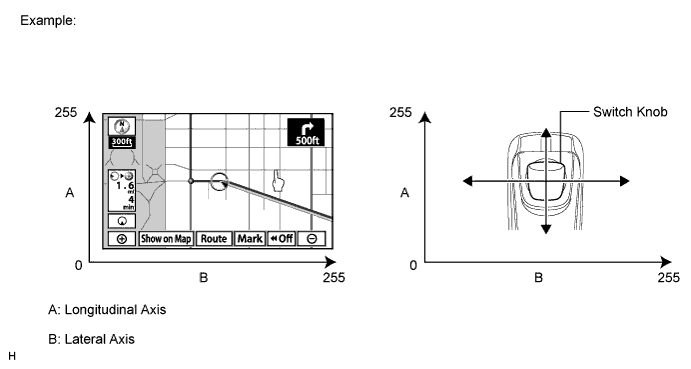
Movement of the pointer on the multi-display screen is synchronized with knob operation.
Remote Touch Switch Knob Feedback Force
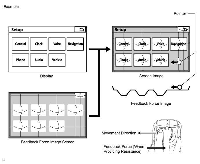
The remote touch has 2 built-in motors. These motors control both lateral and longitudinal axes and generate feedback force according to remote touch switch knob operation.
Icon Area
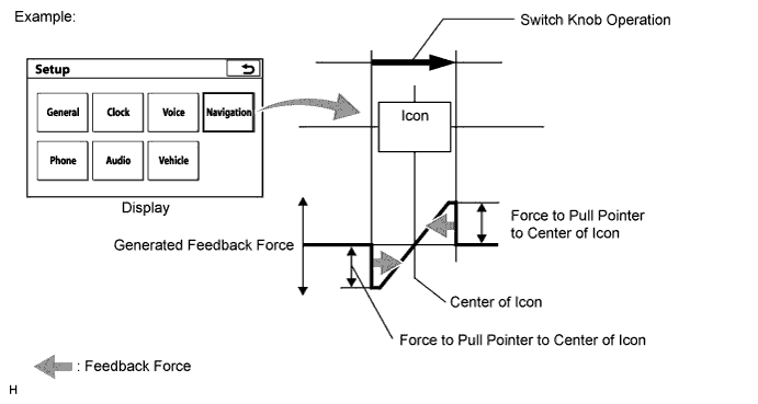
Frame Area
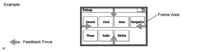
Other Area
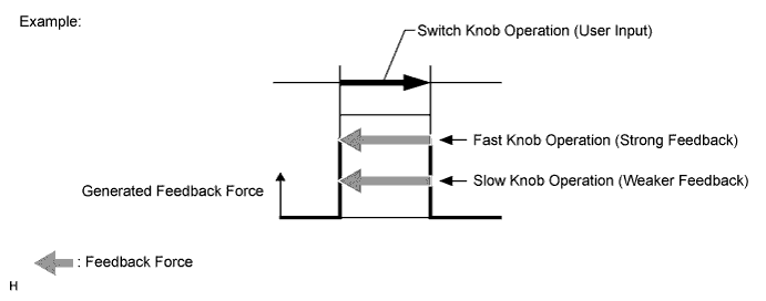
| DVD (DIGITAL VERSATILE DISC) PLAYER OUTLINE (for Navigation Map) |
The navigation module board uses a laser pickup to read the digital signals recorded on a DVD.
| DVD (DIGITAL VERSATILE DISC) PLAYER OUTLINE (for DVD Changer Models) |
The DVD player can only play DVD videos, DVD audio and video CDs that have any of the following marks:

Precaution for use of discs
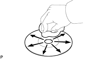 |
Cleaning
If dirt is on the disc surface, wipe it clean with a soft dry cloth such as an eyeglass cleaner for plastic lenses from the inside to the outside in a radial direction.
| RDS-TMC FUNCTION OUTLINE (w/ RDS-TMC Function) |
This system has a function which allows the reception of traffic information from Radio Data System Traffic Message Channel (RDS-TMC) stations based on FM-multiple broadcasting. It assists the driver to avoid areas with traffic congestion. It also helps to improve traffic flow and road safety.
The radio receiver assembly receives RDS-TMC signals and then transmits these signals to the display and navigation module display via the MOST network.
| "Bluetooth" OUTLINE |
"Bluetooth" is a trademark owned by Bluetooth SIG, Inc.
"Bluetooth" is a wireless connection technology that uses the 2.4 GHz frequency band.
Hands-free function
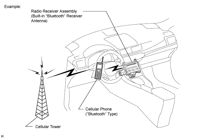
The "Bluetooth" built-in radio receiver assembly and a "Bluetooth" compatible cellular phone*1 can be connected using a "Bluetooth" wireless connection. This enables the use of the hands-free function on the cellular phone even if the phone is in a pocket or bag. For this reason, it is not necessary to use a connector or cable to connect the cellular phone.
*1: Some versions of "Bluetooth" compatible cellular phones may not function.
| COMMUNICATION SYSTEM |
MOST Network Outline
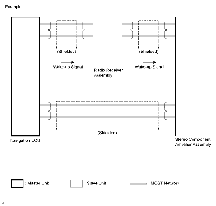
Navigation system components communicate with each other via the MOST network.
The MOST network uses a shielded twisted pair of wires for its communication lines.
The master unit of the MOST network is the navigation ECU (display and navigation module display).
MOST communication lines connect each slave unit centering around the master unit to form a MOST network ring.
The master unit sends a wake-up signal to activate each slave unit connected to the MOST network.
AVC-LAN Outline
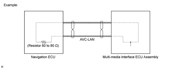
Components of the navigation system communicate with each other via the AVC-LAN.
The AVC-LAN uses a twisted pair of wires for its communication lines.
The master unit of the AVC-LAN is the navigation ECU (display and navigation module display).
| DIAGNOSTIC FUNCTION OUTLINE |
The navigation system has a diagnostic function (the result will be displayed on the master unit or the intelligent tester).
| DIAGNOSIS DISPLAY DETAILED DESCRIPTION |
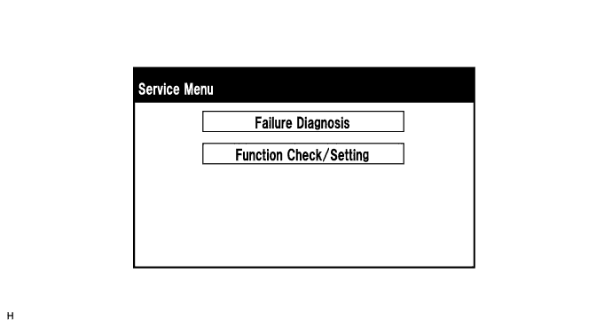
Service Menu Screen
Failure Diagnosis Screen
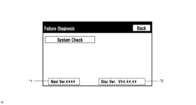
| Display | Content |
| *1: Navi Ver. | Navigation application version |
| *2: Disc Ver. | Map disc version |
System Check Mode Screen
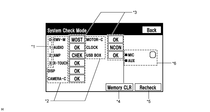
| Name | Component | Connection Method |
| EMV-M | Display and navigation module display | - |
| AUDIO | Radio receiver assembly | Communication line for MOST network |
| AMP | Stereo component amplifier assembly | Communication line for MOST network |
| R-TOUCH | Remote touch | Communication line for MOST network |
| DISP | Multi-display | Communication line for AVC-LAN |
| CAMERA-C | Parking assist ECU | Communication line for AVC-LAN |
| MOTOR-C | Display module board | Communication line for AVC-LAN |
| CLOCK | Center Cluster Module Circuit | Communication line for AVC-LAN |
| USB BOX | Multi-media interface ECU assembly | Communication line for AVC-LAN |
| Result | Meaning | Action |
| OK | The device does not respond with a DTC. | - |
| MOST | MOST communication error | Perform "MOST Line Check" to check the connection of each device on the MOST network. |
| EXCH | The device responds with a "replace"-type DTC. | Look up the DTC in "Unit Check Mode" and replace the device. |
| CHEK | The device responds with a "check"-type DTC. | Look up the DTC in "Unit Check Mode". |
| NCON | The device was previously present, but does not respond in diagnostic mode. | - Check power supply wire harness of the device. - Check the AVC-LAN or MOST network for the device. |
| NRES | The device responds in diagnostic mode, but gives no DTC information. | - Check power supply wire harness of the device. - Check the AVC-LAN or MOST network for the device. |
| Name | Component | Connection Method |
| MIC | Telephone microphone assembly | Vehicle wire harness |
| AUX | No. 1 stereo jack adapter assembly | Vehicle wire harness |
Unit Check Mode Screen
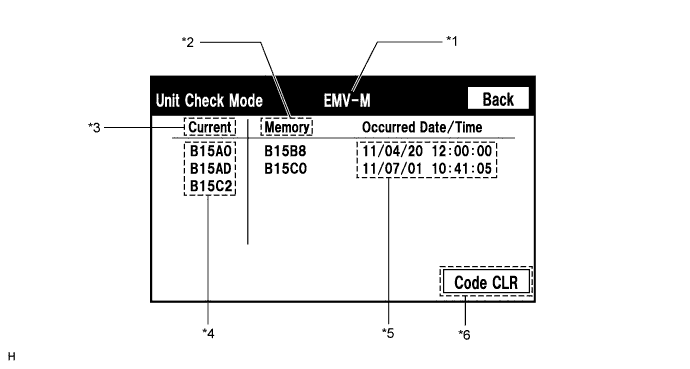
| Display | Content |
| *1: Device name | Target device |
| *2: History DTC | Diagnostic memory results and stored DTCs are displayed. |
| *3: Present DTC | DTCs output in the service check are displayed. |
| *4: DTC | DTC (Diagnostic Trouble Code) |
| *5: Timestamp | The time and date of history DTCs are displayed. (The year is displayed in 2-digit format.) |
| *6: Diagnosis clear switch | Selecting this switch for 3 seconds clears the diagnostic memory data of the target device. (Both response to diagnostic system check result and the displayed data are cleared.) |
MOST Line Check Screen
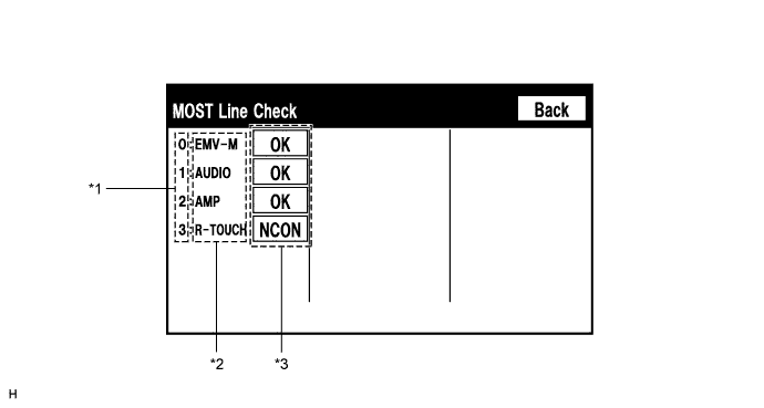
| Name | Component |
| EMV-M | Display and navigation module display |
| AUDIO | Radio receiver assembly |
| AMP | Stereo component amplifier assembly |
| R-TOUCH | Remote touch |
| Result | Meaning |
| OK | There was a response for the connection check during the MOST line check. |
| NCON | There was no response for the connection check during the MOST line check. |
Function Check/Setting Screen
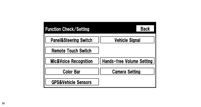
Microphone & Voice Recognition Check Screen
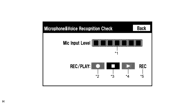
| Display | Content |
| *1: Microphone input level meter | Monitors the microphone input level every 0.1 seconds and displays the results in 8 different levels. |
| *2: Recording switch | Starts recording. |
| *3: Stop switch | Stops recording and playing. |
| *4: Play switch | Plays the recorded voice. |
| *5: Recording indicator | Comes on while recording. |
GPS Information Screen
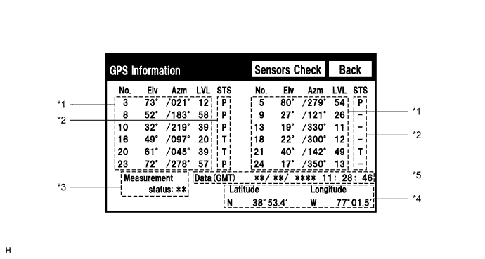
| Display | Content |
| T | The system is receiving a GPS signal, but is not using it for location. |
| P | The system is using the GPS signal for location. |
| - | The system cannot receive a GPS signal. |
| Display | Content |
| 2D | 2-dimensional location method is being used. |
| 3D | 3-dimensional location method is being used. |
| NG | Location data cannot be used. |
| Error | Reception error has occurred. |
| - | Any other state |
| Display | Content |
| Position | Latitude and longitude information on the current position is displayed. |
| Display | Content |
| Data | The date/time information obtained from GPS signals is displayed in Greenwich Mean Time (GMT). |
Vehicle Sensors Screen
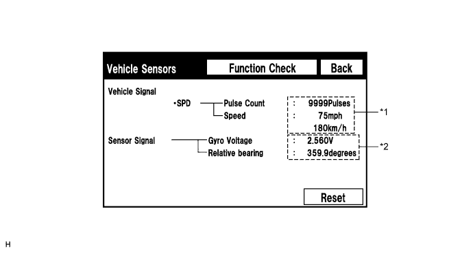
| Display | Content |
| *1: SPD | SPD signal condition is displayed. |
| Display | Content |
| *2: Gyro sensor | Gyro sensor output condition is displayed. |
Vehicle Signal Check Mode Screen
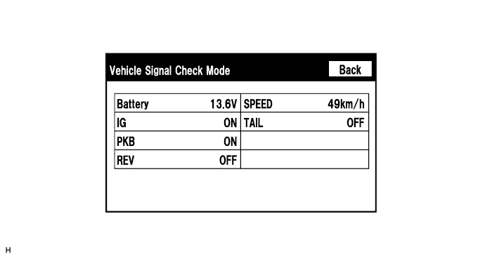
| Display | Content |
| Battery | Auxiliary battery voltage is displayed. |
| IG | Power switch ON/OFF state is displayed. |
| PKB | Parking brake ON/OFF state is displayed. |
| REV | Reverse signal ON/OFF state is displayed. |
| SPEED | Vehicle speed is displayed in km/h. |
| TAIL | TAIL signal (Light control switch) ON/OFF state is displayed. |
