NAVIGATION SYSTEM (for DVD) > Illumination Circuit |
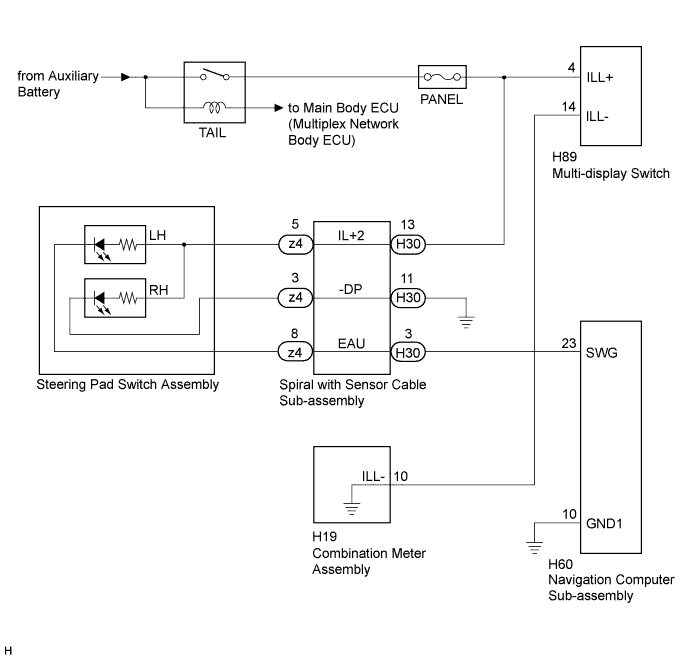
| 1.CHECK ILLUMINATION |
Check if the illumination for the steering pad switch assembly, multi-display switch, glove box or others (hazard switch, etc.) comes on when the light control switch is turned to the tail or head position.
| Result | Proceed to |
| Illumination comes on for all components except steering pad switch. | A |
| Illumination comes on for all components except multi-display switch. | B |
| No illumination comes on (steering pad switch assembly, multi-display switch, glove box, hazard switch, etc.). | C |
|
| ||||
|
| ||||
| A | |
 |
| 2.CHECK HARNESS AND CONNECTOR (ILLUMINATION SIGNAL) |
Disconnect the H30 spiral with sensor cable sub-assembly connector.
Measure the voltage according to the value(s) in the table below.
| Tester Connection | Condition | Specified Condition |
| H30-13 (IL+2) - Body ground | Light control switch in the tail or head position | 11 to 14 V |
|
| ||||
| OK | |
|
| 3.INSPECT SPIRAL WITH SENSOR CABLE SUB-ASSEMBLY |
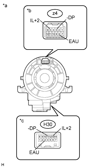 |
Disconnect the z4 steering pad switch assembly and H30 spiral with sensor cable sub-assembly connectors.
Measure the resistance according to the value(s) in the table below.
| Tester Connection | Condition | Specified Condition |
| z4-8 (EAU) - H30-3 (EAU) | Center | Below 1 Ω |
| 2.5 rotations to the left | ||
| 2.5 rotations to the right | ||
| z4-5 (IL+2) - H30-13 (IL+2) | Center | Below 1 Ω |
| 2.5 rotations to the left | ||
| 2.5 rotations to the right | ||
| z4-3 (-DP) - H30-11 (-DP) | Center | Below 1 Ω |
| 2.5 rotations to the left | ||
| 2.5 rotations to the right |
After setting the spiral with sensor cable sub-assembly to the center position, rotate the spiral with sensor cable sub-assembly 2.5 times clockwise. Then while rotating the spiral with sensor cable as shown in the table below.
| Tester Connection | Condition | Specified Condition |
| z4-8 (EAU) - H30-3 (EAU) | Always | Below 1 Ω |
| z4-5 (IL+2) - H30-13 (IL+2) | Always | Below 1 Ω |
| z4-3 (-DP) - H30-11 (-DP) | Always | Below 1 Ω |
| *a | Component without harness connected (Spiral with Sensor Cable Sub-assembly) |
| *b | Steering Pad Switch Assembly Side |
| *c | Vehicle Side |
|
| ||||
| OK | |
|
| 4.CHECK HARNESS AND CONNECTOR |
Disconnect the H60 display and navigation module display connector.
Disconnect the H30 spiral with sensor cable sub-assembly connector.
Measure the resistance according to the value(s) in the table below.
| Tester Connection | Condition | Specified Condition |
| H60-23 (SWG) - H30-3 (EAU) | Always | Below 1 Ω |
| H30-11 (-DP) - Body ground | Always | Below 1 Ω |
| H60-23 (SWG) - Body ground | Always | 10 kΩ or higher |
|
| ||||
| OK | |
|
| 5.INSPECT DISPLAY AND NAVIGATION MODULE DISPLAY |
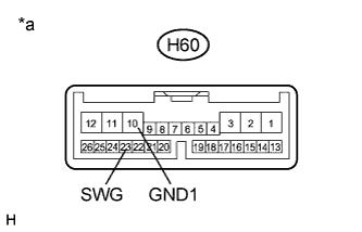 |
Disconnect the H60 display and navigation module display connector.
Measure the resistance according to the value(s) in the table below .
| Tester Connection | Condition | Specified Condition |
| H60-10 (GND1) - H60-23 (SWG) | Always | Below 1 Ω |
| *a | Component without harness connected (Display and Navigation Module Display) |
|
| ||||
| OK | |
|
| 6.INSPECT STEERING PAD SWITCH ASSEMBLY |
Disconnect the z4 steering pad switch assembly connector.
Check that the steering pad switch assembly illuminates according to the table below.
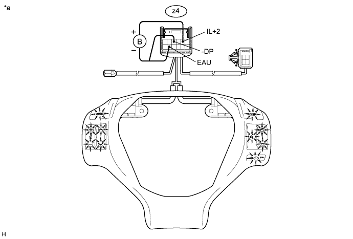
| Connection | Specified Condition |
| Auxiliary battery positive (+) → z4-5 (IL+2) Auxiliary battery negative (-) → z4-8 (EAU) | Switches of steering pad switch LH side illuminates. |
| Auxiliary battery positive (+) → z4-5 (IL+2) Auxiliary battery negative (-) → z4-3 (-DP) | Switches of steering pad switch RH side illuminates. |
| *a | Component without harness connected (Steering Pad Switch Assembly) | - | - |
|
| ||||
| OK | ||
 | ||
| ||
| 7.INSPECT MULTI-DISPLAY SWITCH (MULTI-DISPLAY SWITCH ILLUMINATION) |
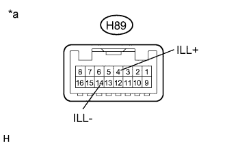 |
Disconnect the H89 multi-display switch connector.
Connect a positive (+) lead to terminal ILL+ and a negative (-) lead from the auxiliary battery to terminal ILL- of the multi-display switch connector.
Check that the multi-display switch illumination comes on.
| *a | Component without harness connected (Multi-display Switch) |
|
| ||||
| OK | |
|
| 8.CHECK HARNESS AND CONNECTOR (ILLUMINATION SIGNAL) |
Disconnect the H89 multi-display switch connector.
Measure the voltage according to the value(s) in the table below.
| Tester Connection | Condition | Specified Condition |
| H89-4 (ILL+) - Body ground | Light control switch in the tail or head position | 11 to 14 V |
|
| ||||
| OK | |
|
| 9.CHECK HARNESS AND CONNECTOR |
Disconnect the H89 multi-display switch connector.
Disconnect the H19 combination meter assembly connector.
Measure the resistance according to the value(s) in the table below.
| Tester Connection | Condition | Specified Condition |
| H89-14 (ILL-) - H19-10 (ILL-) | Always | Below 1 Ω |
| H89-14 (ILL-) - Body ground | Always | 10 kΩ or higher |
|
| ||||
| OK | ||
| ||
| ||


