DTC B1244 Light Sensor Circuit Malfunction |
| DTC No. | DTC Detecting Condition | Trouble Area |
| B1244 |
|
|
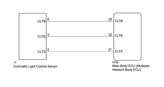
| 1.READ VALUE USING INTELLIGENT TESTER |
Connect the intelligent tester to the DLC3.
Turn the power switch on (IG).
Turn the intelligent tester on.
Enter the following menus: Body / Main Body / Data List.
Read the display on the intelligent tester.
| Tester Display | Measurement Item/Range | Normal Condition | Diagnostic Note |
| Illumination Rate Info | Illumination rate information/0 ms. to 2162.65 ms. | Value is output according to ambient light levels | - |
|
| ||||
| OK | ||
 | ||
| ||
| 2.CHECK HARNESS AND CONNECTOR (MAIN BODY ECU - AUTOMATIC LIGHT CONTROL SENSOR) |
Disconnect the I1 automatic light control sensor connector.
Disconnect the H16 main body ECU (multiplex network body ECU) connector.
Measure the resistance according to the value(s) in the table below.
| Tester Connection | Condition | Specified Condition |
| H16-22 (CLTE) - I1-3 (CLTE) | Always | Below 1 Ω |
| H16-21 (CLTS) - I1-5 (CLTS) | Always | Below 1 Ω |
| H16-20 (CLTB) - I1-6 (CLTB) | Always | Below 1 Ω |
| H16-22 (CLTE) - Body ground | Always | 10 kΩ or higher |
| H16-21 (CLTS) - Body ground | Always | 10 kΩ or higher |
| H16-20 (CLTB) - Body ground | Always | 10 kΩ or higher |
|
| ||||
| OK | |
 |
| 3.INSPECT MAIN BODY ECU (MULTIPLEX NETWORK BODY ECU) |
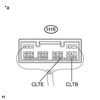 |
Reconnect the H16 main body ECU (multiplex network body ECU) connector.
Measure the voltage and resistance according to the value(s) in the table below.
| Tester Connection | Switch Condition | Specified Condition |
| H16-20 (CLTB) - H16-22 (CLTE) | Power switch off | Below 1 V |
| Power switch on (IG) | 11 to 14 V |
| Tester Connection | Condition | Specified Condition |
| H16-22 (CLTE) - Body ground | Always | Below 1 Ω |
| *a | Component with harness connected (Main Body ECU (Multiplex Network Body ECU)) |
|
| ||||
| OK | |
|
| 4.INSPECT AUTOMATIC LIGHT CONTROL SENSOR |
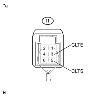 |
Reconnect the I1 automatic light control sensor connector.
Connect an oscilloscope to the automatic light control sensor connector.
| *a | Component with harness connected (Automatic Light Control Sensor) |
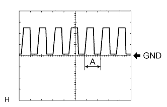 |
Check the waveform.
| Tester Connection | Tool Setting | Condition | Specified Condition |
| I1-3 (CLTE) - I1-5 (CLTS) | 5 V/DIV., 5 ms./DIV. | Power switch on (IG), light control switch in AUTO position | Correct waveform is as shown |
|
| ||||
| OK | ||
| ||
| ||


