LIGHTING SYSTEM > Headlight Dimmer Switch Circuit |
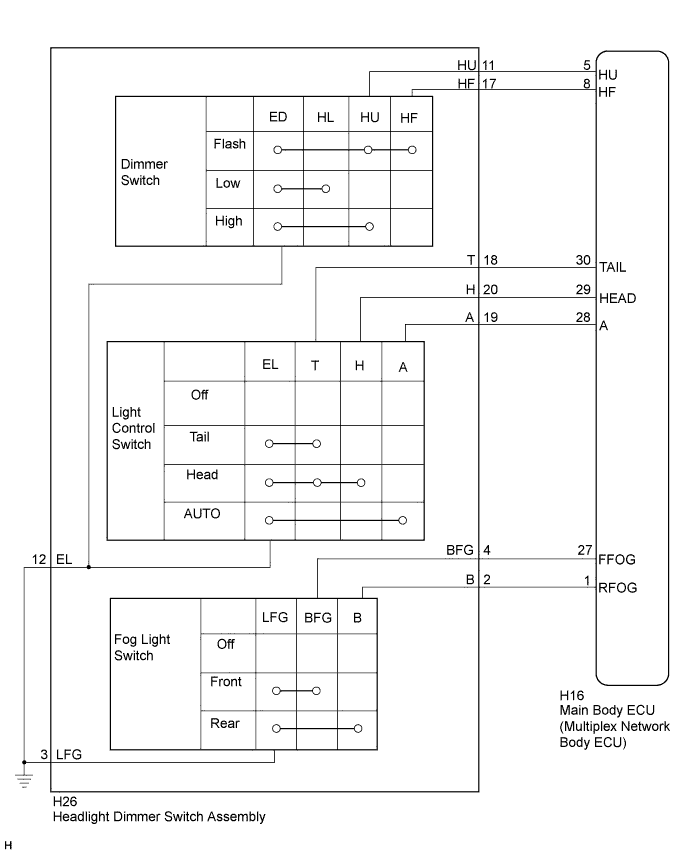
| for LHD, RHD Light Control Switch LH Side Type: |
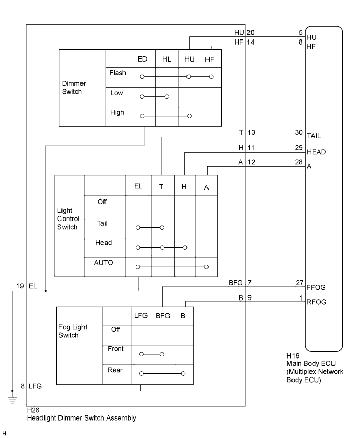
| for RHD Light Control Switch RH Side Type: |
| 1.READ VALUE USING INTELLIGENT TESTER |
Connect the intelligent tester to the DLC3.
Turn the power switch on (IG).
Turn the intelligent tester on.
Enter the following menus: Body / Main Body / Data List.
Read the display on the intelligent tester.
| Tester Display | Measurement Item/Range | Normal Condition | Diagnostic Note |
| Dimmer SW | Dimmer switch high position signal/ON or OFF | ON: Dimmer switch in high or high flash OFF: Dimmer switch in low position | - |
| Passing Light SW | Dimmer switch high flash position (pass) signal/ON or OFF | ON: Dimmer switch in high flash position OFF: Dimmer switch not in high flash position | - |
| Rear Fog Light SW | Rear fog light switch signal/ON or OFF | ON: Rear fog light switch on OFF: Rear fog light switch off | - |
| Front Fog Light SW | Front fog light switch signal/ON or OFF | ON: Front fog light switch on OFF: Front fog light switch off | - |
| Auto Light SW | Light control switch AUTO position signal/ON or OFF | ON: Light control switch in AUTO position OFF: Light control switch not in AUTO position | - |
| Head Light SW (Head) | Light control switch head position signal/ON or OFF | ON: Light control switch in head position OFF: Light control switch not in head position | - |
| Head Light SW (Tail) | Light control switch tail position signal/ON or OFF | ON: Light control switch in tail or head position OFF: Light control switch in neither tail nor head position | - |
|
| ||||
| OK | ||
 | ||
| ||
| 2.INSPECT HEADLIGHT DIMMER SWITCH ASSEMBLY |
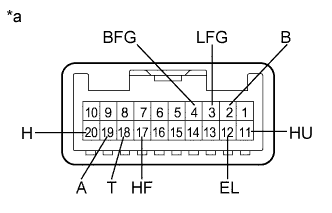 |
Remove the headlight dimmer switch assembly (Click here).
Measure the resistance according to the value(s) in the table below.
| Tester Connection | Switch Condition | Specified Condition |
| 12 (EL) - 18 (T) | Light control switch off | 10 kΩ or higher |
| 18 (T) - 19 (A) | Light control switch off | 10 kΩ or higher |
| 19 (A) - 20 (H) | Light control switch off | 10 kΩ or higher |
| 12 (EL) - 18 (T) | Light control switch in tail position | Below 1 Ω |
| 12 (EL) - 18 (T) | Light control switch in head position | Below 1 Ω |
| 18 (T) - 20 (H) | Light control switch in head position | Below 1 Ω |
| 12 (EL) - 19 (A) | Light control switch in AUTO position | Below 1 Ω |
| Tester Connection | Switch Condition | Specified Condition |
| 11 (HU) - 12 (EL) | Dimmer switch in low position | 10 kΩ or higher |
| 11 (HU) - 12 (EL) | Dimmer switch in high position | Below 1 Ω |
| 12 (EL) - 17 (HF) | Dimmer switch in high flash position | Below 1 Ω |
| Tester Connection | Switch Condition | Specified Condition |
| 3 (LFG) - 4 (BFG) | Fog light switch off | 10 kΩ or higher |
| 3 (LFG) - 4 (BFG) | Fog light switch on | Below 1 Ω |
| Tester Connection | Switch Condition | Specified Condition |
| 3 (LFG) - 2 (B) | Fog light switch off | 10 kΩ or higher |
| 3 (LFG) - 2 (B) | Fog light switch on | Below 1 Ω |
| *a | Component without harness connected (Headlight Dimmer Switch Assembly for LHD, RHD Light Control Switch LH Side Type) |
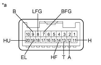 |
Remove the headlight dimmer switch assembly (Click here).
Measure the resistance according to the value(s) in the table below.
| Tester Connection | Switch Condition | Specified Condition |
| 19 (EL) - 13 (T) | Light control switch off | 10 kΩ or higher |
| 13 (T) - 12 (A) | Light control switch off | 10 kΩ or higher |
| 12 (A) - 11 (H) | Light control switch off | 10 kΩ or higher |
| 19 (EL) - 13 (T) | Light control switch in tail position | Below 1 Ω |
| 19 (EL) - 13 (T) | Light control switch in head position | Below 1 Ω |
| 13 (T) - 11 (H) | Light control switch in head position | Below 1 Ω |
| 19 (EL) - 12 (A) | Light control switch in AUTO position | Below 1 Ω |
| Tester Connection | Switch Condition | Specified Condition |
| 20 (HU) - 19 (EL) | Dimmer switch in low position | 10 kΩ or higher |
| 20 (HU) - 19 (EL) | Dimmer switch in high position | Below 1 Ω |
| 19 (EL) - 14 (HF) | Dimmer switch in high flash position | Below 1 Ω |
| Tester Connection | Switch Condition | Specified Condition |
| 8 (LFG) - 7 (BFG) | Fog light switch off | 10 kΩ or higher |
| 8 (LFG) - 7 (BFG) | Fog light switch on | Below 1 Ω |
| Tester Connection | Switch Condition | Specified Condition |
| 8 (LFG) - 9 (B) | Fog light switch off | 10 kΩ or higher |
| 8 (LFG) - 9 (B) | Fog light switch on | Below 1 Ω |
| *a | Component without harness connected (Headlight Dimmer Switch Assembly for RHD Light Control Switch RH Side Type) |
|
| ||||
| OK | |
 |
| 3.CHECK HARNESS AND CONNECTOR (MAIN BODY ECU - HEADLIGHT DIMMER SWITCH ASSEMBLY) |
Disconnect the H26 headlight dimmer switch assembly connector.
Disconnect the H16 main body ECU (multiplex network body ECU) connector.
Measure the resistance according to the value(s) in the table below.
| Tester Connection | Condition | Specified Condition |
| H26-4 (BFG) - H16-27 (FFOG) | Always | Below 1 Ω |
| H26-11 (HU) - H16-5 (HU) | Always | Below 1 Ω |
| H26-17 (HF) - H16-8 (HF) | Always | Below 1 Ω |
| H26-18 (T) - H16-30 (TAIL) | Always | Below 1 Ω |
| H26-19 (A) - H16-28 (A) | Always | Below 1 Ω |
| H26-20 (H) - H16-29 (HEAD) | Always | Below 1 Ω |
| H26-2 (B) - H16-1 (RFOG) | Always | Below 1 Ω |
| H26-4 (BFG) - Body ground | Always | 10 kΩ or higher |
| H26-11 (HU) - Body ground | Always | 10 kΩ or higher |
| H26-17 (HF) - Body ground | Always | 10 kΩ or higher |
| H26-18 (T) - Body ground | Always | 10 kΩ or higher |
| H26-19 (A) - Body ground | Always | 10 kΩ or higher |
| H26-20 (H) - Body ground | Always | 10 kΩ or higher |
| H26-12 (EL) - Body ground | Always | Below 1 Ω |
| H26-3 (LFG) - Body ground | Always | Below 1 Ω |
| H26-2 (B) - Body ground | Always | Below 1 Ω |
| Tester Connection | Condition | Specified Condition |
| H26-7 (BFG) - H16-27 (FFOG) | Always | Below 1 Ω |
| H26-20 (HU) - H16-5 (HU) | Always | Below 1 Ω |
| H26-14 (HF) - H16-8 (HF) | Always | Below 1 Ω |
| H26-13 (T) - H16-30 (TAIL) | Always | Below 1 Ω |
| H26-12 (A) - H16-28 (A) | Always | Below 1 Ω |
| H26-11 (H) - H16-29 (HEAD) | Always | Below 1 Ω |
| H26-9 (B) - H16-1 (RFOG) | Always | Below 1 Ω |
| H26-7 (BFG) - Body ground | Always | 10 kΩ or higher |
| H26-20 (HU) - Body ground | Always | 10 kΩ or higher |
| H26-14 (HF) - Body ground | Always | 10 kΩ or higher |
| H26-13 (T) - Body ground | Always | 10 kΩ or higher |
| H26-12 (A) - Body ground | Always | 10 kΩ or higher |
| H26-11 (H) - Body ground | Always | 10 kΩ or higher |
| H26-19 (EL) - Body ground | Always | Below 1 Ω |
| H26-8 (LFG) - Body ground | Always | Below 1 Ω |
| H26-9 (B) - Body ground | Always | Below 1 Ω |
|
| ||||
| OK | ||
| ||
| ||


