REAR VIEW MONITOR SYSTEM > Inner Rear View Mirror Power Source Circuit |
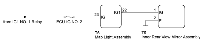
| 1.CHECK HARNESS AND CONNECTOR (BATTERY - INNER REAR VIEW MIRROR ASSEMBLY) |
Disconnect the T9 inner rear view mirror assembly connector.
Measure the voltage according to the value(s) in the table below.
| Tester Connection | Switch Condition | Specified Condition |
| T9-1 (IG) - T9-2 (E) | Power switch on (IG) | 11 to 14 V |
| Power switch off | Below 1 V |
|
| ||||
| OK | ||
 | ||
| ||

