LIGHTING SYSTEM > Headlight Leveling ECU Power Source Circuit |
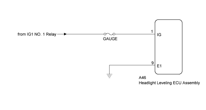
| 1.READ VALUE USING INTELLIGENT TESTER |
Connect the intelligent tester to the DLC3.
Turn the power switch on (IG).
Turn the intelligent tester on.
Enter the following menus: Body / Main Body / Data List.
Read the display on the intelligent tester.
| Tester Display | Measurement Item/Range | Normal Condition | Diagnostic Note |
| +B | IG power supply voltage value / 0 to 19.75 V | 11 to 14 V | - |
|
| ||||
| OK | ||
 | ||
| ||
| 2.CHECK HARNESS AND CONNECTOR (AUXILIARY BATTERY - HEADLIGHT LEVELING ECU ASSEMBLY) |
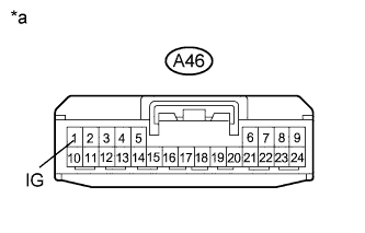 |
Disconnect the A46 headlight leveling ECU assembly connector.
Measure the voltage according to the value(s) in the table below.
| Tester Connection | Switch Condition | Specified Condition |
| A46-1 (IG) - Body ground | Power switch on (IG) | 11 to 14 V |
| A46-1 (IG) - Body ground | Power switch off | Below 1 V |
| *a | Front view of wire harness connector (to Headlight Leveling ECU Assembly) |
|
| ||||
| OK | |
 |
| 3.CHECK HARNESS AND CONNECTOR (HEADLIGHT LEVELING ECU ASSEMBLY - BODY GROUND) |
Measure the resistance according to the value(s) in the table below.
| Tester Connection | Condition | Specified Condition |
| A46-9 (E1) - Body ground | Always | Below 1 Ω |
| Result | Proceed to |
| NG | A |
| OK (for LHD) | B |
| OK (for RHD) | C |
|
| ||||
|
| ||||
| A | ||
| ||
| ||


