POWER MIRROR CONTROL SYSTEM (w/o Memory) > TERMINALS OF ECU |
| CHECK A/C AMPLIFIER ASSEMBLY |
Disconnect the H85 A/C amplifier assembly connector.
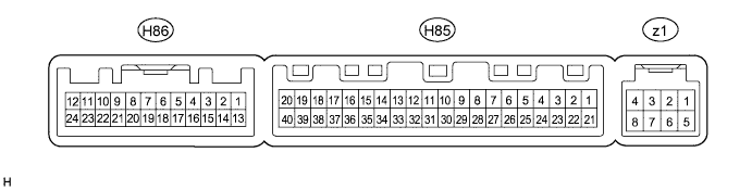
Measure the voltage and resistance according to the value(s) in the table below.
| Tester Connection | Wiring Color | Terminal Description | Condition | Specified Condition |
| H85-1 (IG+) - H85-14 (GND) | B - W-B | Power source (IG) | Power switch on (IG) | 11 to 14 V |
| H85-1 (IG+) - H85-14 (GND) | B - W-B | Power source (IG) | Power switch off | Below 1 V |
| H85-21 (B) - H85-14 (GND) | Y - W-B | ECU power supply | Always | 11 to 14 V |
| H85-14 (GND) - Body ground | W-B - Body ground | Ground | Always | Below 1 Ω |
Reconnect the H85 A/C amplifier assembly connector.
Measure the voltage according to the value(s) in the table below.
| Tester Connection | Wiring Color | Terminal Description | Condition | Specified Condition |
| H85-39 (HRLY) - F47-14 (GND) | R - W-B | Mirror heater switch signal | Power switch on (IG), rear window defogger switch off | 11 to 14 V |
| H85-39 (HRLY) - F47-14 (GND) | R - W-B | Mirror heater switch signal | Power switch on (IG), rear window defogger switch on | Below 1 V |
| CENTER CLUSTER MODULE CIRCUIT (AIR CONDITIONER CONTROL ASSEMBLY) |
Disconnect the H80 center cluster module circuit (air conditioner control assembly) connector.

Measure the voltage and resistance according to the value(s) in the table below.
| Tester Connection | Wiring Color | Terminal Description | Condition | Specified Condition |
| H80-2 (IG+) - Body ground | B - Body ground | Power switch signal | Power switch on (IG) | 11 to 14 V |
| H80-16 (GND) - Body ground | W-B - Body ground | Ground | Always | Below 1 Ω |
Reconnect the H80 A/C control panel assembly connector.
Check for pulses according to the value(s) in the table below.
| Tester Connection | Wiring Color | Terminal Description | Condition | Specified Condition |
| H80-11 (LIN1) - Body ground | V - Body ground | LIN communication signal | Power switch on (IG) | Pulse generation |
