AUDIO AND VISUAL SYSTEM (w/ Navigation System) > Illumination Circuit |
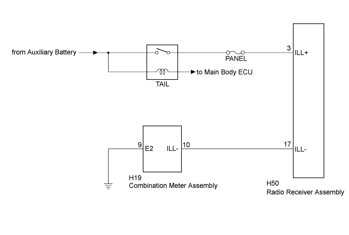
| 1.CHECK ILLUMINATION |
Check if the illumination for the radio receiver assembly, heater control switch or others (hazard switch, etc.) comes on when the light control switch is turned to the head or tail position.
| Result | Proceed to |
| Illumination comes on for all components except radio receiver assembly. | A |
| No illumination comes on (radio receiver assembly, hazard switch, heater control switch, etc.). | B |
|
| ||||
| A | |
 |
| 2.CHECK HARNESS AND CONNECTOR (ILLUMINATION SIGNAL) |
Disconnect the radio receiver assembly connector.
Measure the voltage according to the value(s) in the table below.
| Tester Connection | Condition | Specified Condition |
| H50-3 (ILL+) - Body ground | Light control switch in the tail or head position | 11 to 14 V |
|
| ||||
| OK | |
|
| 3.CHECK HARNESS AND CONNECTOR (RADIO RECEIVER ASSEMBLY - COMBINATION METER ASSEMBLY) |
Disconnect the radio receiver assembly connector and combination meter assembly connector.
Measure the resistance according to the value(s) in the table below.
| Tester Connection | Condition | Specified Condition |
| H50-17 (ILL-) - H19-10 (ILL-) | Always | Below 1 Ω |
| H19-10 (ILL-) - Body ground | Always | 10 kΩ or higher |
|
| ||||
| OK | ||
 | ||
| ||

