AUDIO AND VISUAL SYSTEM (w/o Navigation System) > Illumination Circuit |
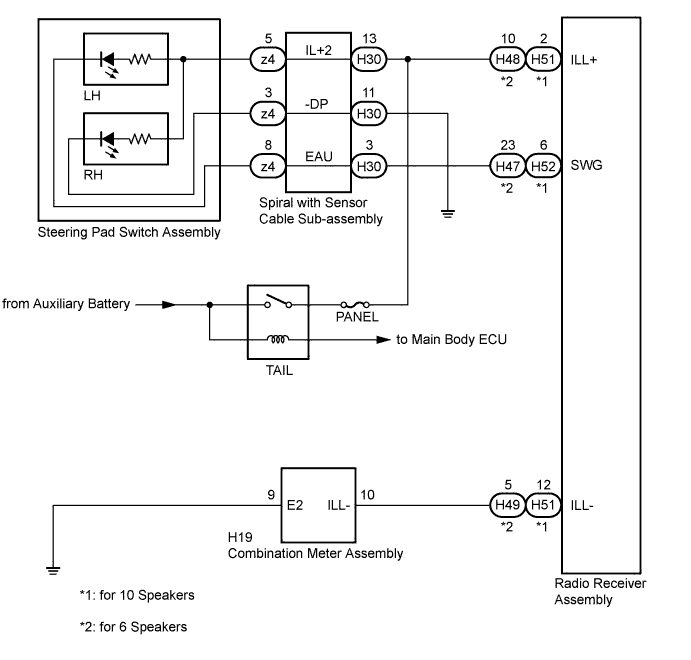
| 1.CHECK ILLUMINATION |
Check if the illumination for the radio receiver assembly, steering pad switch assembly, heater control switch or others (hazard switch, transmission control switch, etc.) comes on when the light control switch is turned to the head or tail position.
| Result | Proceed to |
| Illumination comes on for all components except steering pad switch assembly. | A |
| Illumination comes on for all components except radio receiver assembly. | B |
| No illumination comes on (radio receiver assembly, hazard switch, heater control switch, etc.). | C |
| Illumination comes on only for steering pad switch assembly. | D |
|
| ||||
|
| ||||
|
| ||||
| A | |
 |
| 2.CHECK HARNESS AND CONNECTOR (ILLUMINATION SIGNAL) |
Disconnect the spiral with sensor cable sub-assembly connector.
Measure the voltage according to the value(s) in the table below.
| Tester Connection | Condition | Specified Condition |
| H30-13 (IL+2) - Body ground | Light control switch in the tail or head position | 11 to 14 V |
|
| ||||
| OK | |
|
| 3.INSPECT STEERING PAD SWITCH ASSEMBLY |
Disconnect the steering pad switch assembly connector.
Check that the steering pad switch assembly illuminates according to the table below.
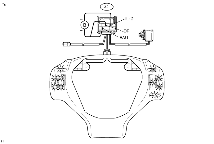
| Connection | Specified Condition |
| Auxiliary battery positive (+) → z4-5 (IL+2) Auxiliary battery negative (-) → z4-8 (EAU) | Switches of steering pad switch LH side illuminates |
| Auxiliary battery positive (+) → z4-5 (IL+2) Auxiliary battery negative (-) → z4-3 (-DP) | Switches of steering pad switch RH side illuminates |
| *a | Component without harness connected (Steering Pad Switch Assembly) | - | - |
|
| ||||
| OK | |
|
| 4.INSPECT SPIRAL WITH SENSOR CABLE SUB-ASSEMBLY |
Disconnect the steering pad switch assembly and spiral with sensor cable sub-assembly connectors.
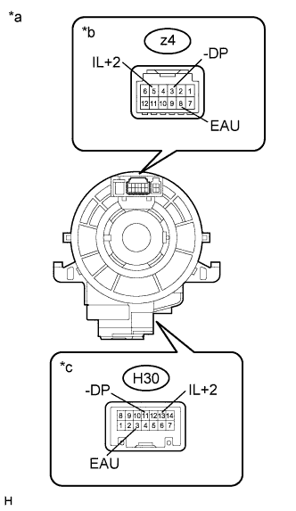 |
Measure the resistance according to the value(s) in the table below.
| Tester Connection | Condition | Specified Condition |
| z4-8 (EAU) - H30-3 (EAU) | Center | Below 1 Ω |
| 2.5 rotations to the left | ||
| 2.5 rotations to the right | ||
| z4-5 (IL+2) - H30-13 (IL+2) | Center | Below 1 Ω |
| 2.5 rotations to the left | ||
| 2.5 rotations to the right | ||
| z4-3 (-DP) - H30-11 (-DP) | Center | Below 1 Ω |
| 2.5 rotations to the left | ||
| 2.5 rotations to the right |
After setting the spiral with sensor cable sub-assembly to the center position, rotate the spiral with sensor cable sub-assembly 2.5 times clockwise. Then while rotating the spiral with sensor cable sub-assembly 5 times counterclockwise, measure the resistance as shown in the table below.
| Tester Connection | Condition | Specified Condition |
| z4-8 (EAU) - H30-3 (EAU) | Always | Below 1 Ω |
| z4-5 (IL+2) - H30-13 (IL+2) | Always | Below 1 Ω |
| z4-3 (-DP) - H30-11 (-DP) | Always | Below 1 Ω |
| *a | Component without harness connected (Spiral with Sensor Cable Sub-assembly) |
| *b | Steering Pad Switch Assembly Side |
| *c | Vehicle Side |
|
| ||||
| OK | |
|
| 5.CHECK HARNESS AND CONNECTOR |
Disconnect the radio receiver assembly and spiral with sensor cable sub-assembly connectors.
Measure the resistance according to the value(s) in the table below.
| Tester Connection | Condition | Specified Condition |
| H30-11 (-DP) - Body ground | Always | Below 1 Ω |
| H52-6 (SWG) - H30-3 (EAU) | Always | Below 1 Ω |
| H52-6 (SWG) - Body ground | Always | 10 kΩ or higher |
| Tester Connection | Condition | Specified Condition |
| H30-11 (-DP) - Body ground | Always | Below 1 Ω |
| H47-23 (SWG) - H30-3 (EAU) | Always | Below 1 Ω |
| H47-23 (SWG) - Body ground | Always | 10 kΩ or higher |
|
| ||||
| OK | ||
 | ||
| ||
| 6.CHECK HARNESS AND CONNECTOR (ILLUMINATION SIGNAL) |
Disconnect the radio receiver assembly connector.
Measure the voltage according to the value(s) in the table below.
| Tester Connection | Condition | Specified Condition |
| H51-2 (ILL+) - Body ground | Light control switch in the tail or head position | 11 to 14 V |
| Tester Connection | Condition | Specified Condition |
| H48-10 (ILL+) - Body ground | Light control switch in the tail or head position | 11 to 14 V |
|
| ||||
| OK | |
|
| 7.CHECK HARNESS AND CONNECTOR (RADIO RECEIVER ASSEMBLY - COMBINATION METER ASSEMBLY) |
Disconnect the radio receiver assembly and combination meter assembly connectors.
Measure the resistance according to the value(s) in the table below.
| Tester Connection | Condition | Specified Condition |
| H51-12 (ILL-) - H19-10 (ILL-) | Always | Below 1 Ω |
| H51-12 (ILL-) - Body ground | Always | 10 kΩ or higher |
| Tester Connection | Condition | Specified Condition |
| H49-5 (ILL-) - H19-10 (ILL-) | Always | Below 1 Ω |
| H49-5 (ILL-) - Body ground | Always | 10 kΩ or higher |
|
| ||||
| OK | ||
| ||
| ||


