AUDIO AND VISUAL SYSTEM (w/o Navigation System) > Stereo Component Amplifier Power Source Circuit |
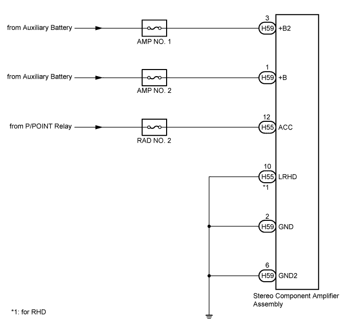
| 1.CHECK HARNESS AND CONNECTOR (POWER SOURCE) |
Disconnect the stereo component amplifier assembly connectors.
Measure the resistance according to the value(s) in the table below.
| Tester Connection | Condition | Specified Condition |
| H59-2 (GND) - Body ground | Always | Below 1 Ω |
| H59-6 (GND2) - Body ground | Always | Below 1 Ω |
| H55-10 (LRHD) - Body ground*1 | Always | Below 1 Ω |
Measure the voltage according to the value(s) in the table below.
| Tester Connection | Condition | Specified Condition |
| H59-1 (+B) - H59-2 (GND) | Power switch off | 11 to 14 V |
| H59-3 (+B2) - H59-2 (GND) | Power switch off | 11 to 14 V |
| H55-12 (ACC) - H59-2 (GND) | Power switch on (ACC) | 11 to 14 V |
|
| ||||
| OK | ||
 | ||
| ||

