AUDIO AND VISUAL SYSTEM (w/o Navigation System) > Steering Pad Switch Circuit |
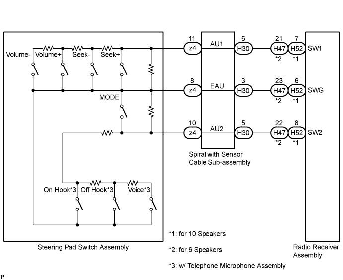
| 1.CHECK HARNESS AND CONNECTOR (STEERING PAD SWITCH SIGNAL) |
Disconnect the radio receiver assembly connector.
Measure the resistance according to the value(s) in the table below.
| Tester Connection | Condition | Specified Condition |
| H52-7 (SW1) - H52-6 (SWG) | No switch pushed | 95 to 105 kΩ |
| Seek+ switch pushed | Below 2.5 Ω | |
| Seek- switch pushed | 313 to 345 Ω | |
| Volume+ switch pushed | 950 to 1050 Ω | |
| Volume- switch pushed | 2955 to 3265 Ω | |
| H52-8 (SW2) - H52-6 (SWG) | No switch pushed | 95 to 105 kΩ |
| MODE switch pushed | Below 2.5 Ω | |
| Voice switch pushed | 2955 to 3265 Ω | |
| On hook switch pushed | 313 to 345 Ω | |
| Off hook switch pushed | 950 to 1050 Ω |
| Tester Connection | Condition | Specified Condition |
| H47-21 (SW1) - H47-23 (SWG) | No switch pushed | 95 to 105 kΩ |
| Seek+ switch pushed | Below 2.5 Ω | |
| Seek- switch pushed | 313 to 345 Ω | |
| Volume+ switch pushed | 950 to 1050 Ω | |
| Volume- switch pushed | 2955 to 3265 Ω | |
| H47-22 (SW2) - H47-23 (SWG) | No switch pushed | 95 to 105 kΩ |
| MODE switch pushed | Below 2.5 Ω | |
| Voice switch pushed*1 | 2955 to 3265 Ω | |
| On hook switch pushed*1 | 313 to 345 Ω | |
| Off hook switch pushed*1 | 950 to 1050 Ω |
|
| ||||
| OK | ||
 | ||
| ||
| 2.INSPECT STEERING PAD SWITCH ASSEMBLY |
Disconnect the steering pad switch assembly connector.
Measure the resistance according to the value(s) in the table below.
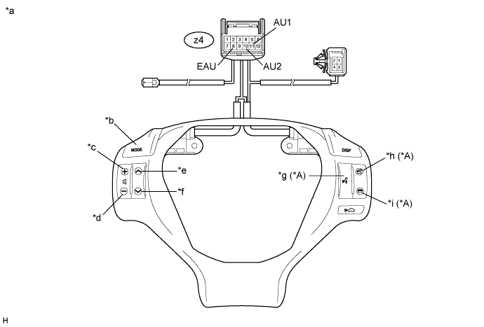
| Tester Connection | Condition | Specified Condition |
| z4-11 (AU1) - z4-8 (EAU) | No switch pushed | 95 to 105 kΩ |
| Seek+ switch pushed | Below 2.5 Ω | |
| Seek- switch pushed | 313 to 345 Ω | |
| Volume+ switch pushed | 950 to 1050 Ω | |
| Volume- switch pushed | 2955 to 3265 Ω | |
| z4-10 (AU2) - z4-8 (EAU) | No switch pushed | 95 to 105 kΩ |
| MODE switch pushed | Below 2.5 Ω | |
| Voice switch pushed*1 | 2955 to 3265 Ω | |
| On hook switch pushed*1 | 313 to 345 Ω | |
| Off hook switch pushed*1 | 950 to 1050 Ω |
| *A | w/ Telephone Microphone Assembly | - | - |
| *a | Component without harness connected (Steering Pad Switch Assembly) | *b | MODE |
| *c | Volume+ | *d | Volume- |
| *e | Seek+ | *f | Seek- |
| *g | Voice | *h | Off Hook |
| *i | On Hook | - | - |
|
| ||||
| OK | |
 |
| 3.INSPECT SPIRAL WITH SENSOR CABLE SUB-ASSEMBLY |
Disconnect the steering pad switch assembly and spiral with sensor cable sub-assembly connectors.
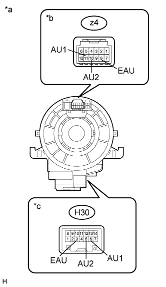 |
Measure the resistance according to the value(s) in the table below.
| Tester Connection | Condition | Specified Condition |
| z4-8 (EAU) - H30-3 (EAU) | Center | Below 1 Ω |
| 2.5 rotations to the left | ||
| 2.5 rotations to the right | ||
| z4-11 (AU1) - H30-6 (AU1) | Center | Below 1 Ω |
| 2.5 rotations to the left | ||
| 2.5 rotations to the right | ||
| z4-10 (AU2) - H30-5 (AU2) | Center | Below 1 Ω |
| 2.5 rotations to the left | ||
| 2.5 rotations to the right |
After setting the spiral with sensor cable sub-assembly to the center position, rotate the spiral with sensor cable sub-assembly 2.5 times clockwise. Then while rotating the spiral with sensor cable sub-assembly 5 times counterclockwise, measure the resistance as shown in the table below.
| Tester Connection | Condition | Specified Condition |
| z4-8 (EAU) - H30-3 (EAU) | Always | Below 1 Ω |
| z4-11 (AU1) - H30-6 (AU1) | Always | Below 1 Ω |
| z4-10 (AU2) - H30-5 (AU2) | Always | Below 1 Ω |
| *a | Component without harness connected (Spiral with Sensor Cable Sub-assembly) |
| *b | Steering Pad Switch Assembly Side |
| *c | Vehicle Side |
|
| ||||
| OK | ||
| ||
| ||


