METER / GAUGE SYSTEM > Entire Combination Meter does not Operate |
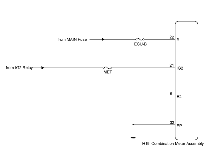
| 1.CHECK HARNESS AND CONNECTOR (COMBINATION METER ASSEMBLY CIRCUIT) |
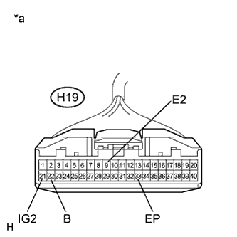 |
Disconnect the H19 connector.
Measure the resistance according to the value(s) in the table below.
| Tester Connection | Condition | Specified Condition |
| H19-9 (E2) - Body ground | Always | Below 1 Ω |
| H19-33 (EP) - Body ground | Always | Below 1 Ω |
Measure the voltage according to the value(s) in the table below.
| Tester Connection | Condition | Specified Condition |
| H19-21 (IG2) - Body ground | Power switch off | Below 1 V |
| Power switch on (IG) | 11 to 14 V | |
| H19-22 (B) - Body ground | Power switch off | 11 to 14 V |
| *a | Front view of wire harness connector (to Combination Meter Assembly) |
|
| ||||
| OK | ||
 | ||
| ||

