METER / GAUGE SYSTEM > Speedometer Malfunction |
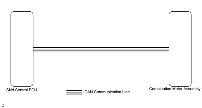
| 1.CHECK CAN COMMUNICATION SYSTEM |
Check if a CAN communication DTC is output (Click here).
| Result | Proceed to |
| CAN communication DTC is not output. | A |
| CAN communication DTC is output. | B |
|
| ||||
| A | |
 |
| 2.PERFORM ACTIVE TEST USING INTELLIGENT TESTER (SPEED METER OPERATION) |
Connect the intelligent tester to the DLC3.
Turn the power switch on (IG).
Turn the intelligent tester on.
Enter the following menus: Body / Combination Meter / Active Test.
Check the operation by referring to the table below.
| Tester Display | Test Part | Control Range | Diagnostic Note |
| Speed Meter Operation | Speedometer | 0, 40, 80, 120 mph*1 | - |
| 0, 40, 80, 120, 160, 200, 240 km/h*2 |
|
| ||||
| OK | |
|
| 3.CHECK BRAKE CONTROL SYSTEM |
Check if the brake control system output the DTC (Click here).
| Result | Proceed to |
| The DTC is not output. | A |
| The DTC is output. | B |
|
| ||||
| A | |
|
| 4.READ VALUE USING INTELLIGENT TESTER (FR/FL/RR/RL WHEEL SPEED, VEHICLE SPEED METER) |
Connect the intelligent tester to the DLC3.
Turn the power switch on (IG).
Turn the intelligent tester on.
Enter the following menus:
for ABS/VSC/TRC: Chassis / ABS/VSC/TRC / Data List.
for Combination Meter: Body / Combination Meter / Data List.
Check the values by referring to the table below.
| Tester Display | Measurement Item/Range | Normal Condition | Diagnostic Note |
| FR Wheel Speed | Vehicle speed/Min.: 0 km/h (0 mph), Max.: 326 km/h (202 mph) | Vehicle stopped: 0 km/h (0 mph) | - |
| FL Wheel Speed | Vehicle speed/Min.: 0 km/h (0 mph), Max.: 326 km/h (202 mph) | Vehicle stopped: 0 km/h (0 mph) | - |
| RR Wheel Speed | Vehicle speed/Min.: 0 km/h (0 mph), Max.: 326 km/h (202 mph) | Vehicle stopped: 0 km/h (0 mph) | - |
| RL Wheel Speed | Vehicle speed/Min.: 0 km/h (0 mph), Max.: 326 km/h (202 mph) | Vehicle stopped: 0 km/h (0 mph) | - |
| Tester Display | Measurement Item/Range | Normal Condition | Diagnostic Note |
| Vehicle Speed Meter | Vehicle speed/Min.: 0 km/h (0 mph), Max.: 255 km/h (158 mph) | Almost the same as actual vehicle speed | - |
| Result | Proceed to |
| The data list values of the ECUs match. | OK |
| The data list values of the ECUs do not match. | NG |
|
| ||||
| OK | ||
 | ||
| ||
| 5.REPLACE COMBINATION METER ASSEMBLY |
Replace the combination meter assembly with a new or a known good one (Click here).
| Result | Proceed to |
| OK | A |
| NG (for LHD) | B |
| NG (for RHD) | C |
|
| ||||
|
| ||||
| A | ||
| ||
| ||


