METER / GAUGE SYSTEM > Malfunction in Water Temperature Warning Light |
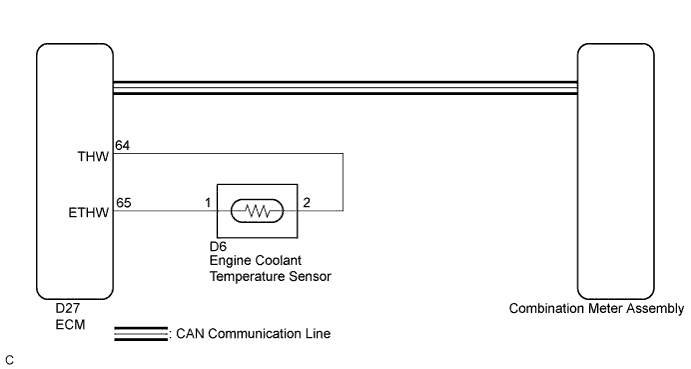
| 1.CHECK CAN COMMUNICATION SYSTEM |
Check if a CAN communication DTC is output (Click here).
| Result | Proceed to |
| CAN communication DTC is not output. | A |
| CAN communication DTC is output. | B |
|
| ||||
| A | |
 |
| 2.SYSTEM CHECK |
Check the water temperature warning light.
| Result | Proceed to |
| Water temperature warning light does not come on. | A |
| Water temperature warning light remains on. | B |
|
| ||||
| A | |
|
| 3.PERFORM ACTIVE TEST USING INTELLIGENT TESTER (COOLANT HOT INDICATOR) |
Connect the intelligent tester to the DLC3.
Turn the power switch on (IG).
Turn the intelligent tester on.
Enter the following menus: Body / Combination Meter / Active Test.
Check the operation by referring to the table below.
| Tester Display | Test Part | Control Range | Diagnostic Note |
| Coolant Hot Indicator | Water temperature warning light | OFF or ON | - |
|
| ||||
| OK | |
|
| 4.CHECK FOR DTC |
Check for the DTC.
| Result | Proceed to |
| No DTC is output. | A |
| DTC P0115 is output. | B |
| DTC B1503 is output. | C |
|
| ||||
|
| ||||
| A | |
|
| 5.READ VALUE USING INTELLIGENT TESTER (COOLANT TEMPERATURE, COOLANT TEMP) |
Connect the intelligent tester to the DLC3.
Turn the power switch on (IG).
Turn the intelligent tester on.
Enter the following menus:
for Combination Meter: Body / Combination Meter / Data List.
for Engine: Powertrain / Engine and ECT / Data List.
Check the values by referring to the table below.
| Tester Display | Measurement Item/Range | Normal Condition | Diagnostic Note |
| Coolant Temperature | Engine coolant temperature/-40 to 127.5°C (-40 to 261.5°F) | After warming up: 75 to 100°C (167 to 212°F) | - |
Check the values by referring to the table below.
| Tester Display | Measurement Item/Range | Normal Condition | Diagnostic Note |
| Coolant Temp | Engine coolant temperature/Min.: -40°C (-40°F), Max.: 140°C (284°F) | After warming up: 75 to 100°C (167 to 212°F) |
|
| Result | Proceed to |
| The data list values of the ECUs do not match. | OK |
| The data list values of the ECUs match. | NG |
|
| ||||
| OK | |
|
| 6.REPLACE COMBINATION METER ASSEMBLY |
Replace the combination meter assembly with a new or a known good one (Click here).
|
| ||||
| OK | ||
 | ||
| ||


