THEFT DETERRENT SYSTEM > Theft Warning Siren Circuit |
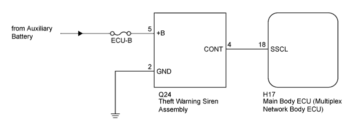
| 1.PERFORM ACTIVE TEST USING INTELLIGENT TESTER |
Connect the intelligent tester to the DLC3.
Turn the power switch to on (IG).
Turn the intelligent tester on.
Enter the following menus: Body / Main Body / Active Test.
Perform the Active Test according to the display on the intelligent tester.
| Tester Display | Test Part | Control Range | Diagnostic Note |
| Security Horn2 | Theft warning siren | ON / OFF | - |
|
| ||||
| OK | ||
 | ||
| ||
| 2.CHECK THEFT WARNING SIREN ASSEMBLY |
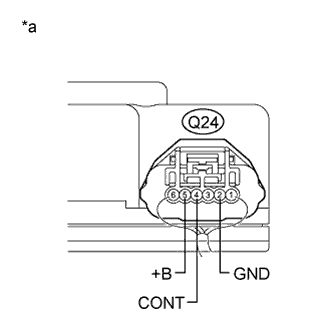 |
Remove the theft warning siren assembly with harness connected (Click here).
Measure the voltage according to the value(s) in the table below.
| Tester Connection | Condition | Specified Condition |
| Q24-5 (+B) - Body ground | Power switch off | 11 to 14 V |
| Q24-2 (GND) - Body ground | Always | Below 1 V |
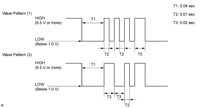
| Q24-4 (CONT) - Body ground | When switched from armed state or arming preparation state to disarmed state (1) or disarmed state (2) (*1) | Wave pattern (1) shown in chart below |
| When switched from arming preparation state to armed state (*2) | Wave pattern (2) shown in chart below | |
| Normal condition (Except (*1) and (*2)) | 11 to 14 V |
| *a | Component with harness connected (Theft Warning Siren Assembly) |
Wave pattern
|
| ||||
| OK | |
 |
| 3.CHECK HARNESS AND CONNECTOR (MAIN BODY ECU - THEFT WARNING SIREN - BODY GROUND) |
Disconnect the H17 main body ECU (multiplex network body ECU) connector.
Disconnect the Q24 theft warning siren assembly connector.
Measure the resistance according to the value(s) in the table below.
| Tester Connection | Condition | Specified Condition |
| H17-18 (SSCL) - Q24-4 (CONT) | Always | Below 1 Ω |
| H17-18 (SSCL) - Body ground | Always | 10 kΩ or higher |
| Q24-2 (GND) - Body ground | Always | Below 1 Ω |
|
| ||||
| OK | ||
| ||
| ||


