DTC B2762 Intrusion Sensor Signal Circuit Malfunction |
| DTC No. | DTC Detection Condition | Trouble Area |
| B2762 | After normal/trouble signal is output from intrusion sensor as result of self-diagnosis, following malfunctions are detected:
|
|
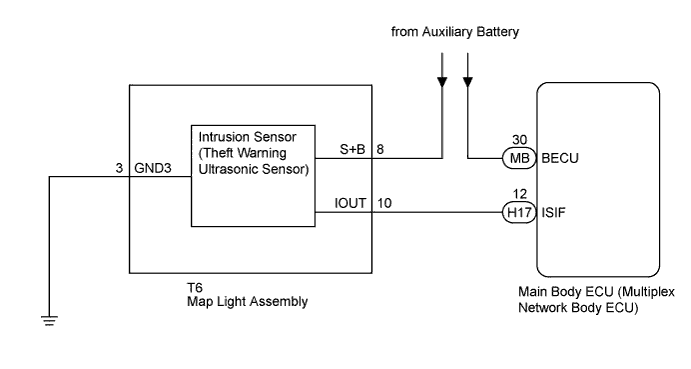
| 1.CHECK HARNESS AND CONNECTOR (MAIN BODY ECU - MAP LIGHT ASSEMBLY) |
Disconnect the H17 main body ECU (multiplex network body ECU) connector.
Disconnect the T6 map light assembly connector.
Measure the resistance according to the value(s) in the table below.
| Tester Connection | Condition | Specified Condition |
| H17-12 (ISIF) - T6-10 (IOUT) | Always | Below 1 Ω |
|
| ||||
| OK | |
 |
| 2.REPLACE MAP LIGHT ASSEMBLY |
Replace the map light assembly (Click here).
| NEXT | |
|
| 3.CHECK FOR DTC |
Clear the DTCs (Click here).
Turn the power switch on (IG), then off.
Set the theft deterrent system to "ARMED STATE".
Check that the security indicator changes from illuminated to blinking.
Set the theft deterrent system to "DISARMED STATE".
Check for DTCs (Click here).
|
| ||||
| OK | ||
 | ||
| ||
| 4.REPLACE INTRUSION SENSOR (THEFT WARNING ULTRASONIC SENSOR) |
Replace the intrusion sensor (theft warning ultrasonic sensor) (Click here).
| NEXT | |
|
| 5.CHECK FOR DTC |
Clear the DTCs (Click here).
Turn the power switch on (IG), then off.
Set the theft deterrent system to "ARMED STATE".
Check that the security indicator changes from illuminated to blinking.
Set the theft deterrent system to "DISARMED STATE".
Check for DTCs (Click here).
|
| ||||
| OK | ||
| ||
| ||


