LIGHTING SYSTEM > Back-up Light Circuit |
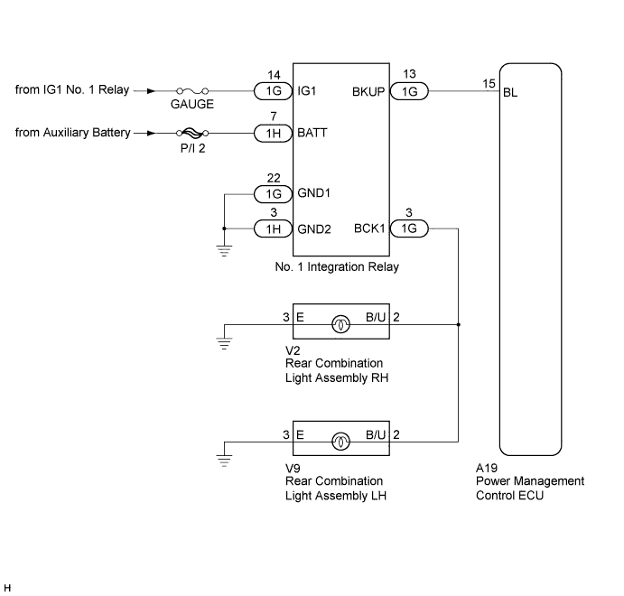
| 1.CHECK FOR DTC (for HYBRID SYSTEM) |
Check for DTCs (Click here).
|
| ||||
| OK | |
 |
| 2.CHECK HARNESS AND CONNECTOR (NO. 1 INTEGRATION RELAY - AUXILIARY BATTERY AND BODY GROUND) |
Disconnect the 1G and 1H No. 1 integration relay connectors.
Measure the voltage and resistance according to the value(s) in the table below.
| Tester Connection | Switch Condition | Specified Condition |
| 1G-14 (IG1) - Body ground | Power switch on (IG) | 11 to 14 V |
| 1H-7 (BATT) - Body ground | Power switch off | 11 to 14 V |
| Tester Connection | Condition | Specified Condition |
| 1G-22 (GND1) - Body ground | Always | Below 1 Ω |
| 1H-3 (GND2) - Body ground | Always | Below 1 Ω |
|
| ||||
| OK | |
|
| 3.CHECK HARNESS AND CONNECTOR (NO. 1 INTEGRATION RELAY - POWER MANAGEMENT CONTROL ECU) |
Disconnect the 1G No. 1 integration relay connector.
Disconnect the A19 power management control ECU connector.
Measure the resistance according to the value(s) in the table below.
| Tester Connection | Condition | Specified Condition |
| 1G-13 (BKUP) - A19-15 (BL) | Always | Below 1 Ω |
| 1G-13 (BKUP) - Body ground | Always | 10 kΩ or higher |
|
| ||||
| OK | |
|
| 4.CHECK HARNESS AND CONNECTOR (REAR COMBINATION LIGHT ASSEMBLY - RELAY AND BODY GROUND) |
Disconnect the 1G No. 1 integration relay connector.
Disconnect the V2 or V9 rear combination light assembly connector.
Measure the resistance according to the value(s) in the table below.
| Tester Connection | Condition | Specified Condition |
| 1G-3 (BCK1) - V2-2 (B/ U) | Always | Below 1 Ω |
| 1G-3 (BCK1) - V9-2 (B/ U) | Always | Below 1 Ω |
| 1G-3 (BCK1) - Body ground | Always | 10 kΩ or higher |
| V2-3 (E) - Body ground | Always | Below 1 Ω |
| V9-3 (E) - Body ground | Always | Below 1 Ω |
|
| ||||
| OK | |
|
| 5.REPLACE NO.1 INTEGRATION RELAY |
Replace the No. 1 integration relay with a new or a known good one (Click here).
Check that the back-up lights operate normally.
|
| ||||
| OK | ||
 | ||
| ||

