DTC C1A05 Stop Light Switch Circuit |
DTC C1A4B Stop Light Relay Circuit |
| DTC No. | DTC Detection Condition | Trouble Area |
| C1A05 | Voltages of terminals ST1- and STP- of driving support ECU assembly are both below 1 V for 1 second |
|
| C1A4B | This trouble code is stored when the brake booster with master cylinder (skid control ECU) detects a malfunction in the stop light control relay circuit for 1 second while the dynamic cruise control is operating. |
|
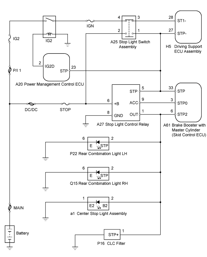
| 1.READ VALUE USING INTELLIGENT TESTER (STOP LIGHT SWITCH ASSEMBLY) |
Connect the intelligent tester to the DLC3.
Turn the power switch on (IG).
Turn the intelligent tester on.
Enter the following menus: Powertrain / Radar Cruise / Data List.
Check the Data List for proper functioning of the stop light switch.
| Tester Display | Measurement Item/Range | Normal Condition | Diagnostic Note |
| Stop Light SW 1 (M CPU) | Stop light switch (Main-CPU) signal / ON or OFF | ON: Brake pedal depressed OFF: Brake pedal released | - |
| Stop Light SW 1 (S CPU) | Stop light switch (Sub-CPU) signal / ON or OFF | ON: Brake pedal depressed OFF: Brake pedal released | - |
| Stop Light SW 2 (M CPU) | Stop light switch (Main-CPU) signal / ON or OFF | ON: Brake pedal depressed OFF: Brake pedal released | - |
|
| ||||
| OK | |
 |
| 2.CHECK HARNESS AND CONNECTOR (STOP LIGHT CONTROL RELAY POWER SOURCE) |
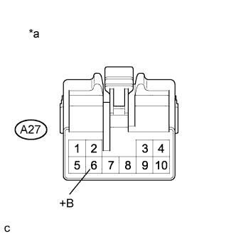 |
Disconnect the stop light control relay connector.
Measure the voltage according to the value(s) in the table below.
| Tester Connection | Condition | Specified Condition |
| A27-6 (+B) - Body ground | Always | 11 to 14 V |
| *a | Front view of wire harness connector (to Stop Light Control Relay) |
Reconnect the stop light control relay connector.
|
| ||||
| OK | |
|
| 3.CHECK HARNESS AND CONNECTOR (STOP LIGHT CONTROL RELAY - BODY GROUND) |
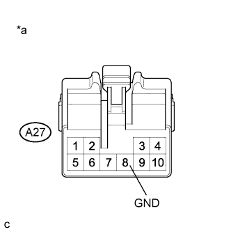 |
Disconnect the stop light control relay connector.
Measure the resistance according to the value(s) in the table below.
| Tester Connection | Condition | Specified Condition |
| A27-8 (GND) - Body ground | Always | Below 1 Ω |
| *a | Front view of wire harness connector (to Stop Light Control Relay) |
Reconnect the stop light control relay connector.
|
| ||||
| OK | |
|
| 4.CHECK HARNESS AND CONNECTOR (STOP LIGHT CONTROL RELAY - STOP LIGHT SWITCH ASSEMBLY) |
Disconnect the stop light control relay connector.
Disconnect the stop light switch assembly connector.
Measure the resistance according to the value(s) in the table below.
| Tester Connection | Condition | Specified Condition |
| A25-1 - A27-5 (STP) | Always | Below 1 Ω |
| Tester Connection | Condition | Specified Condition |
| A25-1 or A27-5 (STP) - Body ground | Always | 10 kΩ or higher |
Reconnect the stop light switch assembly connector.
Reconnect the stop light control relay connector.
|
| ||||
| OK | |
|
| 5.CHECK HARNESS AND CONNECTOR (STOP LIGHT SWITCH ASSEMBLY - SKID CONTROL ECU) |
Disconnect the stop light switch assembly connector.
Disconnect the brake booster with master cylinder (skid control ECU) connector.
Measure the resistance according to the value(s) in the table below.
| Tester Connection | Condition | Specified Condition |
| A25-1 - A61-33 (STP) | Always | Below 1 Ω |
| Tester Connection | Condition | Specified Condition |
| A25-1 or A61-33 (STP) - Body ground | Always | 10 kΩ or higher |
Reconnect the stop light switch assembly connector.
Reconnect the brake booster with master cylinder (skid control ECU) connector.
|
| ||||
| OK | |
|
| 6.CHECK HARNESS AND CONNECTOR (STOP LIGHT CONTROL RELAY - SKID CONTROL ECU) |
Disconnect the stop light control relay connector.
Disconnect the brake booster with master cylinder (skid control ECU) connector.
Measure the resistance according to the value(s) in the table below.
| Tester Connection | Switch Condition | Specified Condition |
| A27-1 (OUT) - A61-6 (STP2) | Always | Below 1 Ω |
| A27-5 (STP) - A61-33 (STP) | Always | Below 1 Ω |
| A27-9 (ACC) - A61-3 (STP0) | Always | Below 1 Ω |
| Tester Connection | Switch Condition | Specified Condition |
| A27-1 (OUT) or A61-6 (STP2) - Body ground | Always | 10 kΩ or higher |
| A27-5 (STP) or A61-33 (STP) - Body ground | Always | 10 kΩ or higher |
| A27-9 (ACC) or A61-3 (STP0) - Body ground | Always | 10 kΩ or higher |
Reconnect the stop light control relay connector.
Reconnect the brake booster with master cylinder (skid control ECU) connector.
|
| ||||
| OK | |
|
| 7.INSPECT STOP LIGHT CONTROL RELAY |
Inspect the stop light control relay (Click here).
|
| ||||
| OK | |
|
| 8.REPLACE BRAKE BOOSTER WITH MASTER CYLINDER (SKID CONTROL ECU) |
Replace the brake booster with master cylinder (skid control ECU) (Click herefor LHD, Click here for RHD ).
| NEXT | |
|
| 9.CHECK WHETHER DTC OUTPUT RECORDS (DTC C1A05 OR C1A4B) |
Connect the intelligent tester to the DLC3.
Turn the power switch on (IG).
Clear the DTCs (Click here).
Perform the following to make sure that the DTC detection conditions are met.
Drive the vehicle at a speed of 50 km/h (30 mph) and 170 km/h (105 mph).
Turn the cruise control switch (ON-OFF button) on.
Push the -/SET switch to activate the cruise control.
Enter the following menus: Powertrain / Radar Cruise / DTC.
Read the DTCs.
| Result | Proceed to |
| DTC is not output | A |
| DTC C1A05 or C104B is output | B |
|
| ||||
| A | ||
 | ||
| ||
| 10.REPLACE POWER MANAGEMENT CONTROL ECU |
Replace the power management control ECU (Click here).
| NEXT | |
|
| 11.CHECK WHETHER DTC OUTPUT RECORDS (DTC C1A05 OR C1A4B) |
Connect the intelligent tester to the DLC3.
Turn the power switch on (IG).
Clear the DTCs (Click here).
Perform the following to make sure that the DTC detection conditions are met.
Drive the vehicle at a speed of 50 km/h (30 mph) and 170 km/h (105 mph).
Turn the cruise control switch (ON-OFF button) on.
Push the -/SET switch to activate the cruise control.
Enter the following menus: Powertrain / Radar Cruise / DTC.
Read the DTCs.
| Result | Proceed to |
| DTC is not output | A |
| DTC C1A05 or C104B is output | B |
|
| ||||
| A | ||
| ||
| ||
| 12.CHECK HARNESS AND CONNECTOR (STOP LIGHT SWITCH ASSEMBLY - POWER SOURCE) |
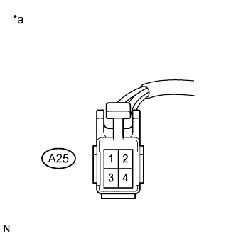 |
Disconnect the stop light switch assembly connector.
Measure the voltage according to the value(s) in the table below.
| Tester Connection | Condition | Specified Condition |
| A25-2 - Body ground | Always | 11 to 14 V |
| *a | Front view of wire harness connector (to Stop Light Switch Assembly) |
Reconnect the stop light switch assembly connector.
|
| ||||
| OK | |
|
| 13.CHECK HARNESS AND CONNECTOR (STOP LIGHT SWITCH ASSEMBLY - POWER SOURCE) |
|
Disconnect the stop light switch assembly connector.
Turn the power switch on (IG).
Measure the voltage according to the value(s) in the table below.
| Tester Connection | Condition | Specified Condition |
| A25-4 - Body ground | Power switch on (IG) | 11 to 14 V |
| *a | Front view of wire harness connector (to Stop Light Switch Assembly) |
Reconnect the stop light switch assembly connector.
|
| ||||
| OK | |
|
| 14.INSPECT STOP LIGHT SWITCH ASSEMBLY |
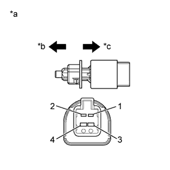 |
Remove the stop light switch assembly (Click here).
Measure the resistance according to the value(s) in the table below.
| Tester Connection | Switch Condition | Specified Condition |
| 1 - 2 | Switch pin not pushed | Below 1 Ω |
| 3 - 4 | Switch pin not pushed | 10 kΩ or higher |
| 1 - 2 | Switch pin pushed | 10 kΩ or higher |
| 3 - 4 | Switch pin pushed | Below 1 Ω |
| *a | Component without harness connected (Stop Light Switch Assembly) |
| *b | Not pushed |
| *c | Pushed |
Reinstall the stop light switch assembly (Click here).
|
| ||||
| OK | |
|
| 15.CHECK HARNESS AND CONNECTOR (STOP LIGHT SWITCH ASSEMBLY - DRIVING SUPPORT ECU ASSEMBLY) |
Disconnect the stop light switch assembly connector.
Disconnect the driving support ECU assembly connector.
Measure the resistance according to the value(s) in the table below.
| Tester Connection | Switch Condition | Specified Condition |
| A25-3 - H5-28 (ST1-) | Always | Below 1 Ω |
| A25-1 - H5-27 (STP-) | Always | Below 1 Ω |
| Tester Connection | Switch Condition | Specified Condition |
| A25-3 or H5-28 (ST1-) - Body ground | Always | 10 kΩ or higher |
| A25-1 or H5-27 (STP-) - Body ground | Always | 10 kΩ or higher |
Reconnect the stop light switch assembly connector.
Reconnect the driving support ECU assembly connector.
|
| ||||
| OK | |
|
| 16.CHECK HARNESS AND CONNECTOR |
Disconnect the stop light switch assembly connector.
Disconnect the driving support ECU assembly connector.
Disconnect the stop light control relay connector.
Disconnect the brake booster with master cylinder (skid control ECU) connector.
Disconnect the power management control ECU connector.
Measure the resistance according to the value(s) in the table below.
| Tester Connection | Switch Condition | Specified Condition |
| A25-1 or H5-27 (STP-) - Body ground | Always | 10 kΩ or higher |
| A25-1 or A61-33 (STP) - Body ground | Always | 10 kΩ or higher |
| A25-1 or A27-5 (STP) - Body ground | Always | 10 kΩ or higher |
| A25-1 or A20-23 (STP) - Body ground | Always | 10 kΩ or higher |
Reconnect the stop light switch assembly connector.
Reconnect the driving support ECU assembly connector.
Reconnect the power management control ECU connector.
Reconnect the stop light control relay connector.
Reconnect the brake booster with master cylinder (skid control ECU) connector.
|
| ||||
| OK | ||
| ||
| ||
| 17.CHECK HARNESS AND CONNECTOR (STOP LIGHT SWITCH ASSEMBLY - STOP LIGHT CONTROL RELAY) |
Disconnect the stop light switch assembly connector.
Disconnect the stop light control relay connector.
Measure the resistance according to the value(s) in the table below.
| Tester Connection | Switch Condition | Specified Condition |
| A25-2 or A27-6 (+B) - Body ground | Always | 10 kΩ or higher |
Reconnect the stop light switch assembly connector.
Reconnect the stop light control relay connector.
|
| ||||
| OK | ||
| ||
| ||


