REAR VIEW MONITOR SYSTEM > TERMINALS OF ECU |
| REAR TELEVISION CAMERA ASSEMBLY |
Disconnect the V8 connector from the rear television camera assembly.

Measure the voltage of each terminal of the wire harness side connector.
| Terminal No. (Symbol) | Wiring Color | Terminal Description | Condition | Specified Condition |
| V8-4 (CB+) - Body ground | B - Body ground | Power source | Power switch on (READY) Reverse (R) selected | 5.5 to 7.0 V |
Reconnect the V8 connector to the rear television camera assembly.
Check for pulses between each terminal of the connector.
| Terminal No. (Symbol) | Wiring Color | Terminal Description | Condition | Specified Condition |
| V8-2 (CV+) - V8-1 (CV-) | R - W | Display signal | Power switch on (READY) Reverse (R) selected Camera lens not covered, displaying an image | Pulse generation (See waveform 1) |
| Power switch on (READY) Reverse (R) selected Camera lens covered, blacking out screen | Pulse generation (See waveform 2) |
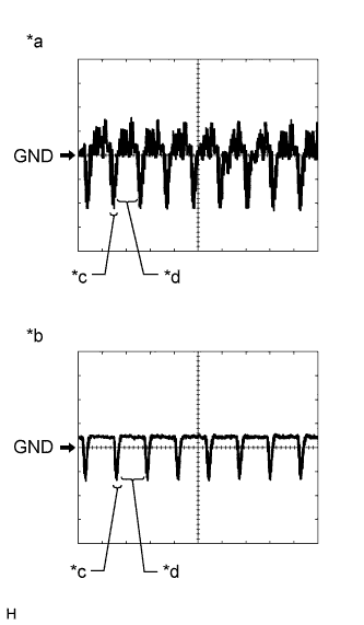 |
Reference (Oscilloscope waveform):
Waveform 1 (camera lens is not covered, displaying an image)
| Item | Content |
| Terminal No. (Symbol) | V8-2 (CV+) - V8-1 (CV-) |
| Tool Setting | 200 mV/DIV., 50 μsec./DIV. |
| Condition | Power switch on (READY), reverse (R) selected |
Waveform 2 (camera lens is covered, blacking out the screen)
| Item | Content |
| Terminal No. (Symbol) | V8-2 (CV+) - V8-1 (CV-) |
| Tool Setting | 200 mV/DIV., 50 μsec./DIV. |
| Condition | Power switch on (READY), reverse (R) selected |
| *a | Waveform 1 (camera lens is not covered, displaying an image) |
| *b | Waveform 2 (camera lens is covered, blacking out the screen) |
| *c | Synchronization Signal |
| *d | Video Waveform |
| INNER REAR VIEW MIRROR ASSEMBLY |
Disconnect the T9 connector from the inner rear view mirror assembly.
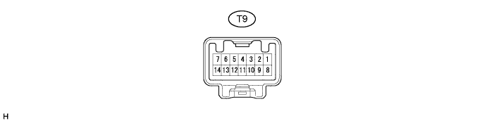
Measure the voltage of each terminal of the wire harness side connector.
| Terminal No. (Symbol) | Wiring Color | Terminal Description | Condition | Specified Condition |
| T9-1 (IG) - Body ground | BE - Body ground | Power switch signal | Power switch off | Below 1 V |
| Power switch on (IG) | 11 to 14 V | |||
| T9-2 (E) - Body ground | W-B - Body ground | Ground | Always | Below 1 V |
| T9-3 (REV) - T9-2 (E) | P - W-B | Reverse signal | Power switch on (READY) Shift state other than reverse (R) selected | Below 1 V |
| Power switch on (READY) Reverse (R) selected | 11 to 14 V | |||
| T9-13 (CGND) - T9-2 (E) | Shielded - W-B | Rear television camera ground (shielded) | Always | Below 1 V |
| T9-14 (CB+) - T9-2 (E) | B - W-B | Power source to television camera | Power switch on (READY) Reverse (R) selected | 5.5 to 7.0 V |
| T9-6 (CV-) - T9-2 (E) | W - W-B | Rear television camera ground | Always | Below 1 V |
Reconnect the T9 connector to the inner rear view mirror assembly.
Check for pulses between each terminal of the connector.
| Terminal No. (Symbol) | Wiring Color | Terminal Description | Condition | Specified Condition |
| T9-7 (CV+) - T9-2 (E) | R - W-B | Display signal | Power switch on (READY) Reverse (R) selected Camera lens not covered, displaying an image | Pulse generation (See waveform 1) |
| Power switch on (READY) Reverse (R) selected Camera lens covered, blacking out screen | Pulse generation (See waveform 2) |
|
Reference (Oscilloscope waveform):
Waveform 1 (camera lens is not covered, displaying an image)
| Item | Content |
| Terminal No. (Symbol) | T9-7 (CV+) - T9-2 (E) |
| Tool Setting | 200 mV/DIV., 50 μsec./DIV. |
| Condition | Power switch on (READY), reverse (R) selected |
Waveform 2 (camera lens is covered, blacking out the screen)
| Item | Content |
| Terminal No. (Symbol) | T9-7 (CV+) - T9-2 (E) |
| Tool Setting | 200 mV/DIV., 50 μsec./DIV. |
| Condition | Power switch on (READY), reverse (R) selected |
| *a | Waveform 1 (camera lens is not covered, displaying an image) |
| *b | Waveform 2 (camera lens is covered, blacking out the screen) |
| *c | Synchronization Signal |
| *d | Video Waveform |
