OUTER REAR VIEW MIRROR > INSPECTION |
| 1. INSPECT OUTER MIRROR ACTUATOR ASSEMBLY RH (w/ Memory) |
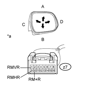 |
Inspect outer mirror motor operation.
Apply auxiliary battery voltage and check the operation of the mirror face as shown in the table and illustration.
| Measurement Condition | Specified Condition |
| Auxiliary battery positive (+) → Terminal 1 (RMVR) Auxiliary battery negative (-) → Terminal 10 (RM+R) | Turns upward (A) |
| Auxiliary battery positive (+) → Terminal 10 (RM+R) Auxiliary battery negative (-) → Terminal 1 (RMVR) | Turns downward (B) |
| Auxiliary battery positive (+) → Terminal 9 (RMHR) Auxiliary battery negative (-) → Terminal 10 (RM+R) | Turns left (C) |
| Auxiliary battery positive (+) → Terminal 10 (RM+R) Auxiliary battery negative (-) → Terminal 9 (RMHR) | Turns right (D) |
| *a | Component without harness connected (Outer Mirror Actuator Assembly RH) |
Inspect outer mirror heater operation.
Apply auxiliary battery voltage and check the operation of the mirror face as shown in the table below.
| Measurement Condition | Specified Condition |
| Auxiliary battery positive (+) → Terminal 4 (HTR+) Auxiliary battery negative (-) → Terminal 12 (HTR-) | Mirror surface temperature becomes higher |
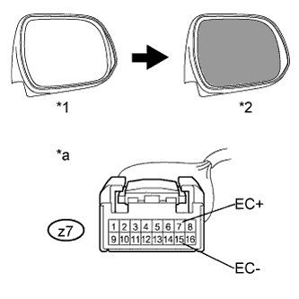 |
Inspect electrochromic outer mirror operation.
Apply auxiliary battery voltage and check the operation of the mirror face as shown in the table and illustration.
| Measurement Condition | Specified Condition |
| Auxiliary battery positive (+) → Terminal 7 (EC+) Auxiliary battery negative (-) → Terminal 15 (EC-) | Mirror surface changes to dark |
| *1 | Bright |
| *2 | Dark |
| *a | Component without harness connected (Outer Rear View Mirror Assembly RH) |
| 2. INSPECT OUTER MIRROR ACTUATOR ASSEMBLY LH (w/ Memory) |
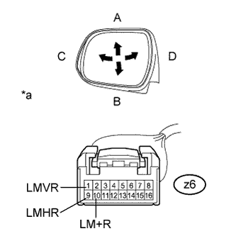 |
Inspect outer mirror motor operation.
Apply auxiliary battery voltage and check the operation of the mirror face as shown in the table and illustration.
| Measurement Condition | Specified Condition |
| Auxiliary battery positive (+) → Terminal 1 (LMVR) Auxiliary battery negative (-) → Terminal 10 (LM+R) | Turns upward (A) |
| Auxiliary battery positive (+) → Terminal 10 (LM+R) Auxiliary battery negative (-) → Terminal 1 (LMVR) | Turns downward (B) |
| Auxiliary battery positive (+) → Terminal 9 (LMHR) Auxiliary battery negative (-) → Terminal 10 (LM+R) | Turns left (C) |
| Auxiliary battery positive (+) → Terminal 10 (LM+R) Auxiliary battery negative (-) → Terminal 9 (LMHR) | Turns right (D) |
| *a | Component without harness connected (Outer Mirror Actuator Assembly LH) |
Inspect outer mirror heater operation.
Apply auxiliary battery voltage and check the operation of the mirror face as shown in the table below.
| Measurement Condition | Specified Condition |
| Auxiliary battery positive (+) → Terminal 4 (HTR+) Auxiliary battery negative (-) → Terminal 12 (HTR-) | Mirror surface temperature becomes higher |
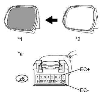 |
Inspect electrochromic outer mirror operation.
Apply auxiliary battery voltage and check the operation of the mirror face as shown in the table and illustration.
| Measurement Condition | Specified Condition |
| Auxiliary battery positive (+) → Terminal 7 (EC+) Auxiliary battery negative (-) → Terminal 15 (EC-) | Mirror surface changes to dark |
| *1 | Dark |
| *2 | Bright |
| *a | Component without harness connected (Outer Rear View Mirror Assembly LH) |
| 3. INSPECT OUTER MIRROR ACTUATOR ASSEMBLY RH (w/o Memory) |
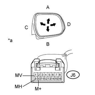 |
Inspect outer mirror motor operation.
Apply auxiliary battery voltage and check the operation of the mirror face as shown in the table and illustration.
| Measurement Condition | Specified Condition |
| Auxiliary battery positive (+) → Terminal 1 (MV) Auxiliary battery negative (-) → Terminal 10 (M+) | Turns upward (A) |
| Auxiliary battery positive (+) → Terminal 10 (M+) Auxiliary battery negative (-) → Terminal 1 (MV) | Turns downward (B) |
| Auxiliary battery positive (+) → Terminal 9 (MH) Auxiliary battery negative (-) → Terminal 10 (M+) | Turns left (C) |
| Auxiliary battery positive (+) → Terminal 10 (M+) Auxiliary battery negative (-) → Terminal 9 (MH) | Turns right (D) |
| *a | Component without harness connected (Outer Mirror Actuator Assembly RH) |
Inspect outer mirror heater operation.
Apply auxiliary battery voltage and check the operation of the mirror face as shown in the table below.
| Measurement Condition | Specified Condition |
| Auxiliary battery positive (+) → Terminal 4 (+) Auxiliary battery negative (-) → Terminal 12 (-) | Mirror surface temperature becomes higher |
| 4. INSPECT OUTER MIRROR ACTUATOR ASSEMBLY LH (w/o Memory) |
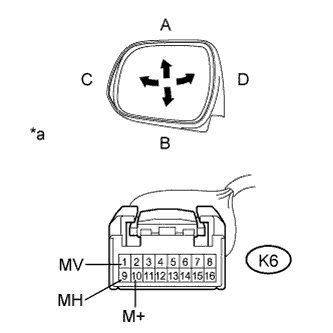 |
Inspect outer mirror motor operation.
Remove the outer rear view mirror assembly LH.
Apply auxiliary battery voltage and check the operation of the mirror face as shown in the table and illustration.
| Measurement Condition | Specified Condition |
| Auxiliary battery positive (+) → Terminal 1 (MV) Auxiliary battery negative (-) → Terminal 10 (M+) | Turns upward (A) |
| Auxiliary battery positive (+) → Terminal 10 (M+) Auxiliary battery negative (-) → Terminal 1 (MV) | Turns downward (B) |
| Auxiliary battery positive (+) → Terminal 9 (MH) Auxiliary battery negative (-) → Terminal 10 (M+) | Turns left (C) |
| Auxiliary battery positive (+) → Terminal 10 (M+) Auxiliary battery negative (-) → Terminal 9 (MH) | Turns right (D) |
| *a | Component without harness connected (Outer Mirror Actuator Assembly LH) |
Inspect outer mirror heater operation.
Apply auxiliary battery voltage and check the operation of the mirror face as shown in the table below.
| Measurement Condition | Specified Condition |
| Auxiliary battery positive (+) → Terminal 4 (+) Auxiliary battery negative (-) → Terminal 12 (-) | Mirror surface temperature becomes higher |
