AUTOMATIC LIGHT CONTROL SENSOR > INSPECTION |
| 1. INSPECT AUTOMATIC LIGHT CONTROL SENSOR |
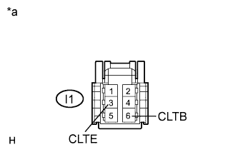 |
Disconnect the I1 automatic light control sensor connector.
Measure the voltage and resistance according to the value(s) in the table below.
| Tester Connection | Switch Condition | Specified Condition |
| I1-6 (CLTB) - I1-3 (CLTE) | Power switch off | Below 1 V |
| Power switch on (IG) | 10 to 14 V |
| Tester Connection | Condition | Specified Condition |
| I1-3 (CLTE) - Body ground | Always | Below 1 Ω |
| *a | Front view of wire harness connector (to Automatic Light Control Sensor) |
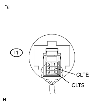 |
Reconnect the I1 automatic light control sensor connector.
Connect an oscilloscope to the automatic light control sensor connector.
| *a | Component with harness connected (Automatic Light Control Sensor) |
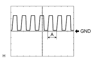 |
Check the waveform.
| Tester Connection | Tool Setting | Switch Condition | Specified Condition |
| I1-3 (CLTE) - I1-5 (CLTS) | 5 V/DIV., 5 ms./DIV | Power switch on (IG), light control switch in AUTO position | Correct waveform is as shown |
