HEADLIGHT LEVELING SWITCH > INSPECTION |
| 1. INSPECT HEADLIGHT LEVELING SWITCH |
Voltage Ratio Inspection.
Disconnect connector H135 from the headlight leveling switch.
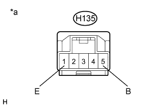 |
Using SST, measure the voltage between terminals H135-5 (B) and H135-1 (E). (Voltage A)
| *a | Front side of wire harness connector (to Headlight Leveling Switch) |
Connect connector H135 to the headlight leveling switch.
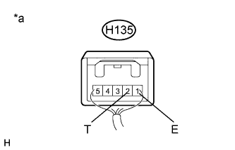 |
Using SST, measure the voltage between terminals H135-2 (T) and H135-1 (E) from backside of the connector. (Voltage B)
Divide Voltage B by Voltage A to obtain the voltage ratio.
| Switch Position | Voltage Ratio (%) |
| 0 | 7 to 13 |
| (0.5) | 12.3 to 18.3 |
| 1 | 17.7 to 23.7 |
| (1.5) | 23.0 to 29.0 |
| 2 | 28.3 to 34.3 |
| (2.5) | 33.7 to 39.7 |
| 3 | 39.0 to 45.0 |
| (3.5) | 44.7 to 50.3 |
| 4 | 49.7 to 55.7 |
| (4.5) | 55.0 to 61.0 |
| 5 | 60.3 to 66.3 |
| *a | Component with harness connected (Headlight Leveling Switch) |
 |
LED Illumination Inspection
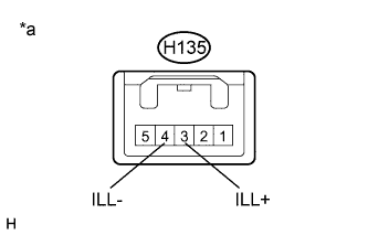
Connect the negative and positive battery terminals to the connector according to the table below.
| Tester Connection | Switch Condition | Specified Condition |
| 3 (ILL+) - 4 (ILL-) | Battery positive (+) a 3 (ILL+) Battery negative (-) a 4 (ILL-) | Illuminates |
| *a | Connector disconnected (to Headlight Leveling Switch) |
