DTC B156F No Response from Motor Control |
DTC B1560 Motor Control Disconnected |
| DTC No. | DTC Detection Condition | Trouble Area |
| B156F | No response to the diagnostic memory request from the master unit. |
|
| B1560*1 | A device that is listed in the AVC-LAN connected device record of the master unit is missing. |
| 1.CHECK OPTIONAL COMPONENTS (INCLUDING ASSOCIATED WIRING) |
Check for optional components
Check that optional components (including associated wiring) which generate radio waves are not installed.
| Result | Proceed to |
| Optional components (including associated wiring) are installed. | A |
| Optional components (including associated wiring) are not installed. | B |
|
| ||||
| A | |
 |
| 2.REMOVE OPTIONAL COMPONENTS (INCLUDING ASSOCIATED WIRING) |
Remove optional components (including associated wiring).
| NEXT | |
|
| 3.CHECK DTC |
Clear the DTCs (Click here).
Recheck for DTCs and check if the same DTC is output again.
|
| ||||
| OK | ||
 | ||
| ||
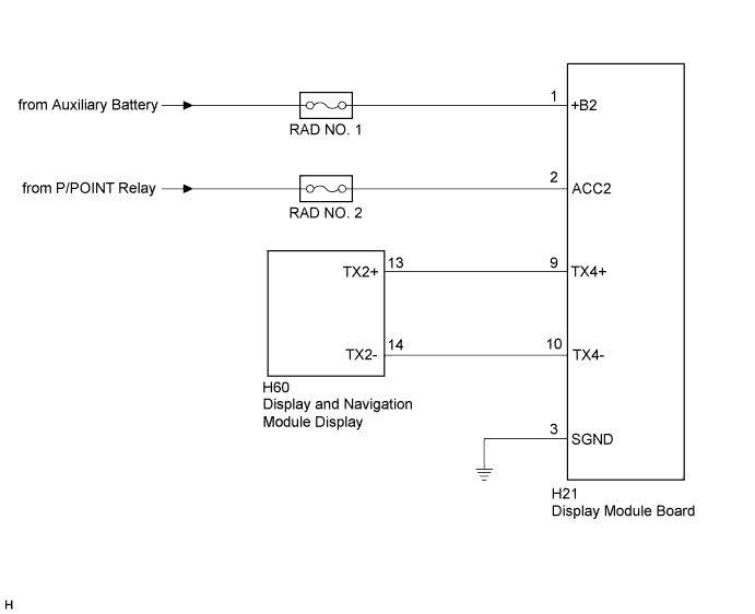
| 4.CHECK HARNESS AND CONNECTOR (DISPLAY MODULE BOARD POWER SOURCE) |
Disconnect the H21 display module board connector.
Measure the resistance according to the value(s) in the table below.
| Tester Connection | Condition | Specified Condition |
| H21-3 (SGND) - Body ground | Always | Below 1 Ω |
Measure the voltage according to the value(s) in the table below.
| Tester Connection | Condition | Specified Condition |
| H21-1 (+B2) - H21-3 (SGND) | Power switch off | 11 to 14 V |
| H21-2 (ACC2) - H21-3 (SGND) | Power switch on (ACC) | 11 to 14 V |
|
| ||||
| OK | |
|
| 5.CHECK HARNESS AND CONNECTOR |
Disconnect the H21 display module board connector.
Disconnect the H60 display and navigation module display connector.
Measure the resistance according to the value(s) in the table below.
| Tester Connection | Condition | Specified Condition |
| H21-9 (TX4+) - H60-13 (TX2+) | Always | Below 1 Ω |
| H21-10 (TX4-) - H60-14 (TX2-) | Always | Below 1 Ω |
| H21-9 (TX4+) - Body ground | Always | 10 kΩ or higher |
| H21-10 (TX4-) - Body ground | Always | 10 kΩ or higher |
|
| ||||
| OK | |
|
| 6.REPLACE DISPLAY MODULE BOARD |
Replace the display module board (Click here).
Clear the DTCs (Click here).
Recheck for DTCs and check if the same DTC is output again.
|
| ||||
| OK | ||
| ||
| ||


