DTC B1584 Panel Switch Malfunction |
| DTC No. | DTC Detection Condition | Trouble Area |
| B1584 | Multi-display switch malfunction |
|
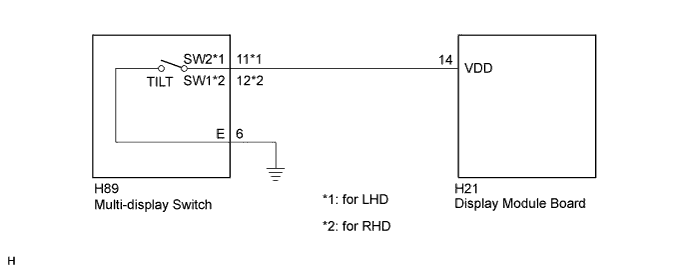
| 1.CHECK DTC |
Clear the DTC (Click here).
Recheck for DTCs and check if the same DTC is output again.
|
| ||||
| OK | ||
 | ||
| ||
| 2.INSPECT MULTI-DISPLAY SWITCH |
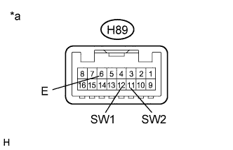 |
Disconnect the H89 multi-display switch connector.
Measure the resistance according to the value(s) in the table below.
| Tester Connection | Condition | Specified Condition |
| H89-11 (SW2) - H89-6 (E) | "TILT" switch not pressed | 10 kΩ or higher |
| H89-11 (SW2) - H89-6 (E) | "TILT" switch pressed | Below 1 Ω |
| Tester Connection | Condition | Specified Condition |
| H89-12 (SW1) - H89-6 (E) | "TILT" switch not pressed | 10 kΩ or higher |
| H89-12 (SW1) - H89-6 (E) | "TILT" switch pressed | Below 1 Ω |
| *a | Component without harness connected (Multi-display Switch) |
|
| ||||
| OK | |
 |
| 3.CHECK HARNESS AND CONNECTOR |
Disconnect the H89 multi-display switch connector.
Disconnect the H21display module board.
Measure the resistance according to the value(s) in the table below.
| Tester Connection | Condition | Specified Condition |
| H89-11 (SW2) - H21-14 (VDD) | Always | Below 1 Ω |
| H89-11 (SW2) - Body ground | Always | 10 kΩ or higher |
| H89-6 (E) - Body ground | Always | Below 1 Ω |
| Tester Connection | Condition | Specified Condition |
| H89-12 (SW1) - H21-14 (VDD) | Always | Below 1 Ω |
| H89-12 (SW1) - Body ground | Always | 10 kΩ or higher |
| H89-6 (E) - Body ground | Always | Below 1 Ω |
|
| ||||
| OK | ||
| ||
| ||


