DTC B15B0 Display Screen Malfunction |
| DTC No. | DTC Detection Condition | Trouble Area |
| B15B0 | Picture circuit (TFT unit) malfunction |
|
| Multi-display open/close function malfunction |
|
| 1.CLEAR DTC |
Clear the DTC (Click here).
| NEXT | |
 |
| 2.CHECK FOREIGN OBJECT |
Check the area around the center instrument cluster finish panel assembly for obstacles or protrusions which may interrupt opening/closing of the multi-display, and also check for foreign objects stuck in moving parts. If any foreign objects are present, remove them.
| NEXT | |
|
| 3.CHECK DTC |
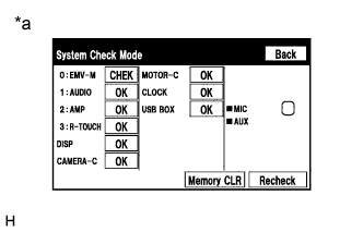 |
Display the "System Check Mode" screen (Click here).
Check result on the "System Check Mode" screen.
| Result | Proceed to |
| The trouble area cannot be determined using the "System Check Mode" screen due to a multi-display malfunction. | A |
| DTC "B15B0" is output from "EMV-M". | B |
| DTC "B15B0" is output from "DISP". | C |
| The trouble area cannot be determined using the "System Check Mode" screen because the multi-display does not open when the power switch is turned on (ACC). | D |
| DTC "B15B0" is output from "MOTOR-C". | D |
| No DTCs are output. | E |
| *a | Example |
|
| ||||
|
| ||||
|
| ||||
|
| ||||
| A | |
|
| 4.REPLACE MULTI-DISPLAY |
Replace the multi-display (Click here).
Clear the DTCs (Click here).
Recheck for DTCs and check if the same DTC is output again.
|
| ||||
| OK | ||
 | ||
| ||
| 5.CHECK CENTER INSTRUMENT CLUSTER FINISH PANEL ASSEMBLY (DRIVING PART USED FOR DRIVEN PART OF MULTI-DISPLAY) |
Check that there is no damage on the driving parts that drive the multi-display and that no foreign objects are caught (Click here).
| Result | Proceed to |
| Damage on the driving parts. | A |
| Foreign objects are caught between the driving parts. | B |
| No damage on the driving parts and no foreign objects are caught between the driving parts. | C |
|
| ||||
|
| ||||
| A | |
|
| 6.REPLACE DAMAGED DRIVING PART |
Replace damaged driving parts (Click here).
Clear the DTCs (Click here).
Recheck for DTCs and check if the same DTC is output again.
|
| ||||
| OK | ||
| ||
| ||
| 7.REMOVE FOREIGN OBJECT |
Remove foreign objects caught between the driving parts.
Clear the DTCs (Click here).
Recheck for DTCs and check if the same DTC is output again.
|
| ||||
| OK | ||
| ||
| ||
| 8.REPLACE MULTI-DISPLAY CONTROLLER SUB-ASSEMBLY |
Replace the multi-display controller sub-assembly (Click here).
Clear the DTCs (Click here).
Recheck for DTCs and check if the same DTC is output again.
|
| ||||
| OK | ||
| ||
| ||
| 9.REPLACE SENSOR WIRE |
Replace the sensor wire (Click here).
Clear the DTCs (Click here).
Recheck for DTCs and check if the same DTC is output again.
|
| ||||
| OK | ||
| ||
| ||


