NAVIGATION SYSTEM (for DVD) > AVC-LAN Circuit |
| 1.INSPECT DISPLAY AND NAVIGATION MODULE DISPLAY |
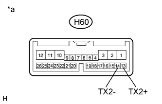 |
Disconnect the H60 display and navigation module display connector.
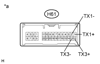 |
Disconnect the H61 display and navigation module display connector.
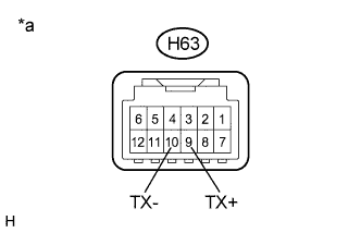 |
Disconnect the H63 display and navigation module display connector.
Measure the resistance according to the value(s) in the table below.
| Tester Connection | Condition | Specified Condition |
| H60-13 (TX2+) - H60-14 (TX2-) | Always | 60 to 80 Ω |
| H61-1 (TX1+) - H61-2 (TX1-) | Always | 60 to 80 Ω |
| H61-12 (TX3+) - H61-13 (TX3-) | Always | 60 to 80 Ω |
| H63-9 (TX+) - H63-10 (TX-) | Always | 60 to 80 Ω |
| *a | Component without harness connected (Display and Navigation Module Display) |
|
| ||||
| OK | |
 |
| 2.CHECK HARNESS AND CONNECTOR (AVC-LAN CIRCUIT) |
Referring to the AVC-LAN wiring diagram below, check all AVC-LAN circuits.
Disconnect all connectors in all AVC-LAN circuits.
Check for an open or short in all AVC-LAN circuits.
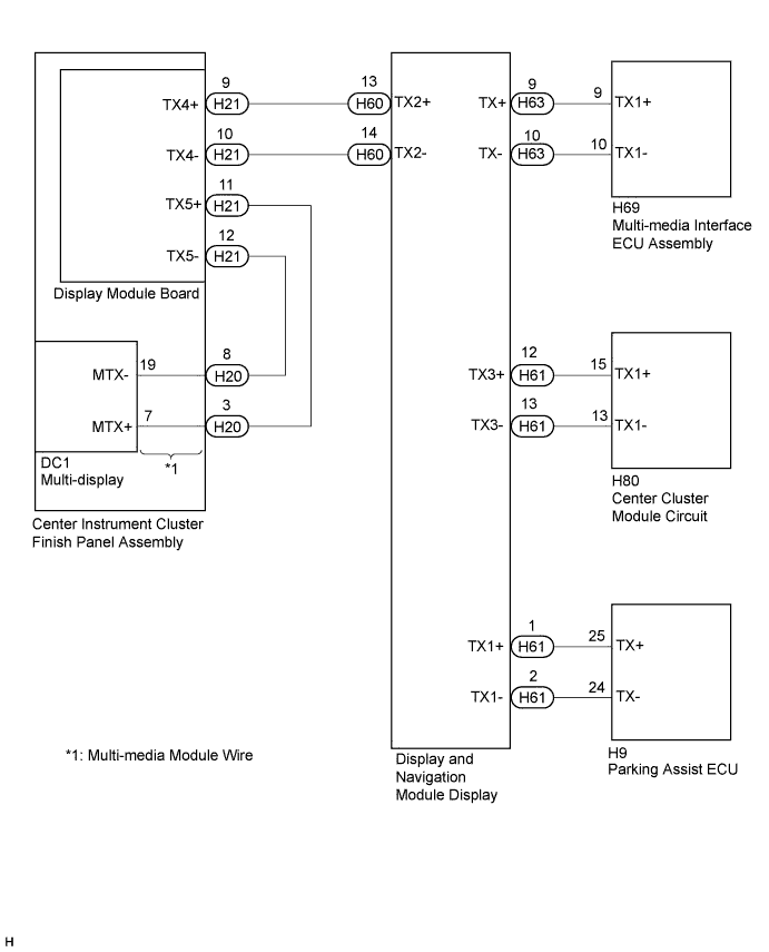
|
| ||||
| OK | |
|
| 3.INSPECT MALFUNCTIONING PARTS |
Disconnect and reconnect each slave unit one by one until the master unit returns to normal operation.
|
| ||||
| OK | ||
 | ||
| ||

