LIGHTING SYSTEM > High Beam Headlight Circuit |
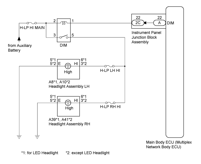
| 1.CHECK OPERATION (LOW BEAM HEADLIGHTS) |
Check the operation of the low beam headlights.
|
| ||||
| OK | |
 |
| 2.PERFORM ACTIVE TEST USING INTELLIGENT TESTER |
Connect the intelligent tester to the DLC3.
Turn the power switch on (IG).
Turn the intelligent tester on.
Enter the following menus: Body / Main Body / Active Test.
Check that the high beam headlights illuminate.
| Tester Display | Test Part | Control Range | Diagnostic Note |
| Head Light Hi | High beam headlights | ON/OFF | - |
|
| ||||
| OK | ||
 | ||
| ||
| 3.INSPECT HEADLIGHT DIMMER RELAY (DIM) |
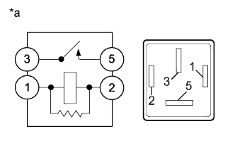 |
Remove the headlight dimmer relay from the engine room relay block.
Measure the resistance according to the value(s) in the table below.
| Tester Connection | Condition | Specified Condition |
| 3 - 5 | Voltage is not applied between terminals 1 and 2 | 10 kΩ or higher |
| 3 - 5 | Voltage is applied between terminals 1 and 2 | Below 1 Ω |
| *a | Component without harness connected (Headlight Dimmer Relay) |
|
| ||||
| OK | |
|
| 4.CHECK HARNESS AND CONNECTOR (H-LP HI MAIN FUSE - HEADLIGHT DIMMER RELAY) |
Measure the voltage according to the value(s) in the table below.
| Tester Connection | Condition | Specified Condition |
| Headlight dimmer relay terminal 2 - Body ground | Power switch off | 11 to 14 V |
| Headlight dimmer relay terminal 3 - Body ground | Power switch off | 11 to 14 V |
|
| ||||
| OK | |
|
| 5.CHECK HARNESS AND CONNECTOR (HEADLIGHT DIMMER RELAY - HEADLIGHT ASSEMBLY) |
Disconnect the A8 or A39 headlight assembly connector (for LED headlight).
Disconnect the A10 or A41 headlight assembly connector (except LED headlight).
Measure the resistance according to the value(s) in the table below.
| Tester Connection | Condition | Specified Condition |
| 5 - A8-6 (HI) | Always | Below 1 Ω |
| 5 - Body ground | Always | 10 kΩ or higher |
| A8-5 (E) - Body ground | Always | Below 1 Ω |
| Tester Connection | Condition | Specified Condition |
| 5 - A39-6 (HI) | Always | Below 1 Ω |
| 5 - Body ground | Always | 10 kΩ or higher |
| A39-5 (E) - Body ground | Always | Below 1 Ω |
| Tester Connection | Condition | Specified Condition |
| 5 - A10-3 (HI) | Always | Below 1 Ω |
| 5 - Body ground | Always | 10 kΩ or higher |
| A10-5 (E) - Body ground | Always | Below 1 Ω |
| Tester Connection | Condition | Specified Condition |
| 5 - A41-3 (HI) | Always | Below 1 Ω |
| 5 - Body ground | Always | 10 kΩ or higher |
| A41-5 (E) - Body ground | Always | Below 1 Ω |
|
| ||||
| OK | |
|
| 6.CHECK HARNESS AND CONNECTOR (HEADLIGHT DIMMER RELAY - MAIN BODY ECU) |
Disconnect the 2C main body ECU (multiplex network body ECU) connector.
Measure the resistance according to the value(s) in the table below.
| Tester Connection | Condition | Specified Condition |
| Headlight dimmer relay terminal 1 - 2C-22 | Always | Below 1 Ω |
| 2C-22 - Body ground | Always | 10 kΩ or higher |
|
| ||||
| OK | |
|
| 7.CHECK INSTRUMENT PANEL JUNCTION BLOCK ASSEMBLY |
Remove the instrument panel junction block assembly.
Measure the resistance according to the value(s) in the table below.
| Tester Connection | Condition | Specified Condition |
| 2C-22 - A-22 (DIM) | Always | Below 1 Ω |
|
| ||||
| OK | ||
| ||
| ||


