REAR BRAKE > INSTALLATION |
| 1. INSTALL REAR DISC |
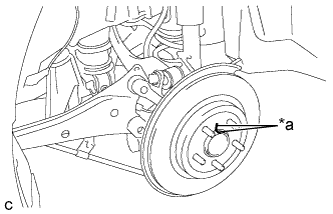 |
Align the matchmarks of the disc and axle hub, and install the disc.
| *a | Matchmark |
| 2. INSTALL DISC BRAKE CYLINDER MOUNTING |
Install the disc brake cylinder mounting with the 2 bolts.
| 3. INSTALL REAR DISC BRAKE BUSHING DUST BOOT |
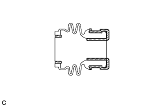 |
Apply a light layer of lithium soap base glycol grease to the entire circumference of 2 new rear disc brake bushing dust boots.
 | Lithium Soap Base Glycol Grease |
Install the 2 rear disc brake bushing dust boots to the disc brake cylinder mounting.
| 4. INSTALL REAR DISC BRAKE PAD GUIDE PIN |
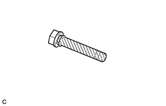 |
Apply a light layer of lithium soap base glycol grease to the sliding and sealing surfaces of the 2 rear disc brake pad guide pins.
| Lithium Soap Base Glycol Grease |
Install the 2 rear disc brake pad guide pins to the disc brake cylinder mounting.
| 5. INSTALL REAR DISC BRAKE PAD SUPPORT PLATE |
Install the 2 rear disc brake pad support plates to the disc brake cylinder mounting.
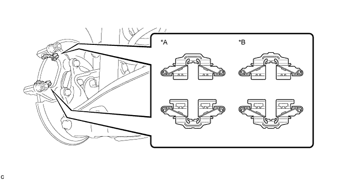
| *A | for Disc Diameter 259 mm (10.2 in.) | *B | for Disc Diameter 279 mm (11.0 in.) |
| 6. INSTALL REAR DISC BRAKE ANTI-SQUEAL SHIM |
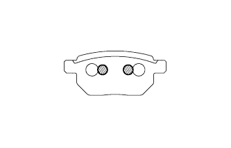 |
Apply disc brake grease to the back plate of the rear disc brake pads.
| Disc Brake Grease |
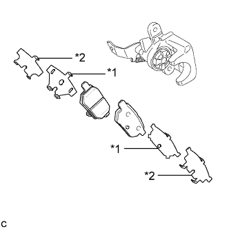 |
Install the rear No. 1 disc brake anti-squeal shim and rear No. 2 disc brake anti-squeal shim to each rear disc brake pad.
| *1 | Rear No. 1 Disc Brake Anti-squeal Shim |
| *2 | Rear No. 2 Disc Brake Anti-squeal Shim |
| 7. INSTALL REAR DISC BRAKE PAD |
Install the 2 rear disc brake pads to the disc brake cylinder mounting.
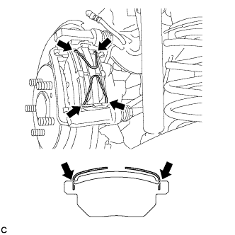 |
Install the 2 anti-squeal springs to the rear disc brake pads.
| 8. INSTALL REAR DISC BRAKE CYLINDER ASSEMBLY |
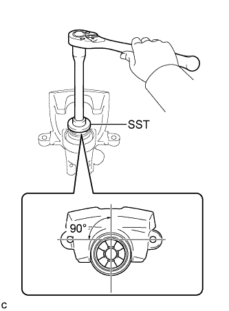 |
To compensate for pad lining thickness, use SST to adjust the protrusion of the rear disc brake piston by turning it.
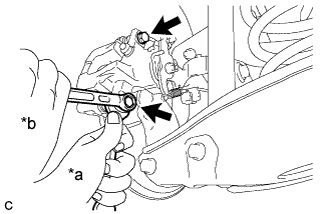 |
Hold the rear disc brake cylinder pad guide pin, and install the rear disc brake cylinder assembly to the disc brake cylinder mounting with the 2 bolts.
| *a | Hold |
| *b | Turn |
| 9. CONNECT REAR FLEXIBLE HOSE |
Connect the rear flexible hose to the rear disc brake cylinder assembly with a new union bolt and a new gasket.
| 10. CONNECT NO. 3 PARKING BRAKE CABLE ASSEMBLY |
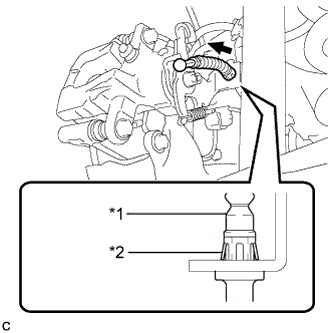 |
Install the No. 3 parking brake cable assembly to the rear disc brake cylinder assembly.
| *1 | No. 3 Parking Brake Cable Assembly |
| *2 | Clip |
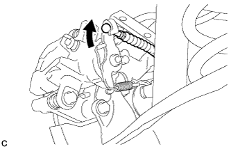 |
Connect the No. 3 parking brake cable assembly to the rear disc brake cylinder assembly.
Install the No. 3 parking brake cable assembly with the bolt.
| 11. INSTALL PARKING BRAKE LEVER PROTECTOR |
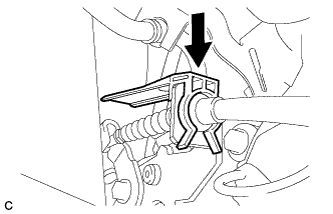 |
Install the parking brake lever protector to the No. 3 parking brake cable assembly.
| 12. FILL RESERVOIR WITH BRAKE FLUID |
| 13. CONNECT CABLE TO NEGATIVE AUXILIARY BATTERY TERMINAL |
Connect the cable to the negative (-) auxiliary battery terminal (Click here).
Perform the following procedure if air bleeding is not necessary:
Connect the reservoir level switch connector.
Clear the DTCs (Click here).
| 14. BLEED BRAKE LINE |
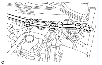 |
Disengage the 5 claws and 2 guides to remove the center cowl top ventilator louver.
Bleed brake line.
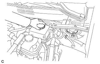 |
Remove the brake master cylinder reservoir filler cap assembly.
Add brake fluid into the reservoir between MAX and MIN level on the brake fluid reservoir.
Connect the intelligent tester to the DLC3 and turn the power switch on (IG).
Turn the intelligent tester on and enter the following menus: Chassis / ABS/VSC/TRC / Air Bleeding.
Select "Usual air bleeding" on the intelligent tester display, and bleed air from the brake fluid following the instructions on the intelligent tester.
After air bleeding, tighten each bleeder plug.
Clear the DTCs (Click here).
Turn the intelligent tester off and turn the power switch off.
Inspect for brake fluid leaks.
Install the brake master cylinder reservoir filler cap.
|
Engage the 5 claws and 2 guides to install the center cowl top ventilator louver.
| 15. ADJUST PARKING BRAKE |
| 16. INSTALL LOWER INSTRUMENT PANEL FINISH PANEL SUB-ASSEMBLY (for LHD) |
Connect each connector.
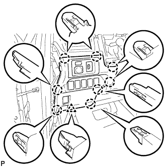 |
Engage the 8 claws and clip to install the lower instrument panel finish panel sub-assembly.
| 17. INSTALL INSTRUMENT SIDE PANEL LH (for LHD) |
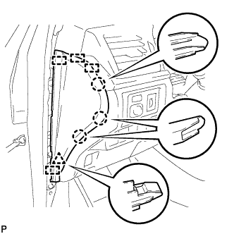 |
Engage the 4 guides, clip and 3 claws to install the instrument side panel LH.
| 18. INSTALL FRONT DOOR OPENING TRIM WEATHERSTRIP LH (for LHD) |
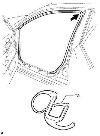 |
Align the alignment mark (orange) on the weatherstrip with the protruding portion on the body indicated by the arrow in the illustration, and install the front door opening trim weatherstrip LH.
| *a | Alignment Mark (Orange) |
| 19. INSTALL NO. 1 INSTRUMENT PANEL UNDER COVER SUB-ASSEMBLY (for LHD) |
Connect each connector.
Engage the clamp.
Engage the clip.
Install the No. 1 instrument panel under cover sub-assembly with the 2 screws <E>.
| 20. INSTALL NO. 2 AIR DUCT SUB-ASSEMBLY (for RHD) |
Engage the 2 claws to install the No. 2 air duct sub-assembly.
| 21. INSTALL NO. 1 INSTRUMENT PANEL UNDER COVER SUB-ASSEMBLY (for RHD) |
Connect each connector.
Engage the clamp.
Engage the 2 clips.
Install the No. 1 instrument panel under cover sub-assembly with the screw <E>.
| 22. INSTALL REAR WHEEL |
