REAR BRAKE > REMOVAL |
| 1. PRECAUTION |
| 2. DISABLE BRAKE CONTROL |
Wait at least 2 minutes after the power switch off.
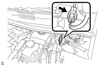 |
Disconnect the reservoir level switch connector with the parking brake applied.
Disconnect the cable from the negative (-) auxiliary battery terminal (Click here).
Depress the brake pedal 40 times or more to return all the fluid in the accumulator back to the reservoir.
Check that the brake pedal can not be further depressed.
Release the parking brake.
| 3. REMOVE REAR WHEEL |
| 4. DRAIN BRAKE FLUID |
| 5. REMOVE NO. 1 INSTRUMENT PANEL UNDER COVER SUB-ASSEMBLY (for LHD) |
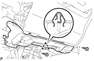 |
Remove the 2 screws <E>.
Disengage the clip.
Disengage the clamp.
Disconnect each connector and remove the No. 1 instrument panel under cover sub-assembly.
| 6. DISCONNECT FRONT DOOR OPENING TRIM WEATHERSTRIP LH (for LHD) |
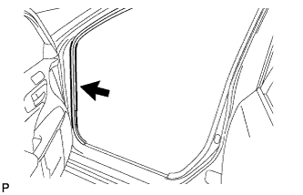 |
Disconnect the front door opening trim weatherstrip.
Remove the residual weatherstrip sealant from the body of the vehicle using cleaner.
| 7. REMOVE INSTRUMENT SIDE PANEL LH (for LHD) |
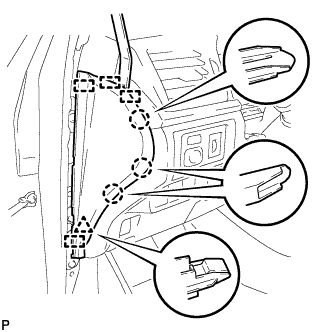 |
Using a moulding remover, disengage the 3 claws, clip and 4 guides, and remove the instrument side panel LH.
| 8. REMOVE LOWER INSTRUMENT PANEL FINISH PANEL SUB-ASSEMBLY (for LHD) |
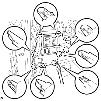 |
Using a moulding remover, disengage the 8 claws and clip.
Disconnect each connector and remove the lower instrument panel finish panel sub-assembly.
| 9. LOOSEN PARKING BRAKE CABLE (for LHD) |
Completely release the parking brake pedal.
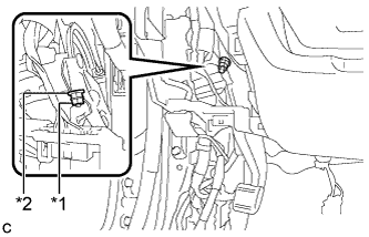 |
Loosen the lock nut and adjusting nut to completely release the parking brake cable.
| *1 | Lock Nut |
| *2 | Adjusting Nut |
| 10. REMOVE NO. 1 INSTRUMENT PANEL UNDER COVER SUB-ASSEMBLY (for RHD) |
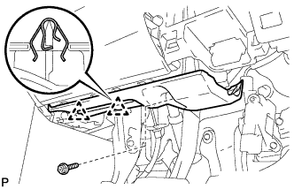 |
Remove the screw <E>.
Disengage the 2 clips.
Disengage the clamp.
Disconnect each connector and remove the No. 1 instrument panel under cover sub-assembly.
| 11. REMOVE NO. 2 AIR DUCT SUB-ASSEMBLY (for RHD) |
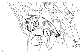 |
Disengage the 2 claws to remove the No. 2 air duct sub-assembly.
| 12. LOOSEN PARKING BRAKE CABLE (for RHD) |
Completely release the parking brake pedal.
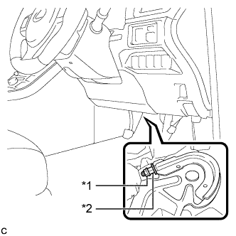 |
Loosen the lock nut and the adjusting nut to completely release the parking brake cable.
| *1 | Lock Nut |
| *2 | Adjusting Nut |
| 13. REMOVE PARKING BRAKE LEVER PROTECTOR |
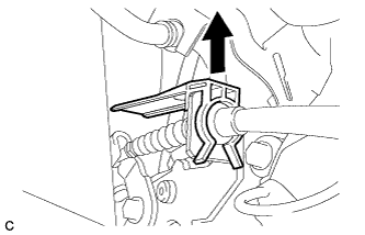 |
Remove the parking brake lever protector from the No. 3 parking brake cable assembly.
| 14. DISCONNECT NO. 3 PARKING BRAKE CABLE ASSEMBLY |
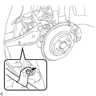 |
Remove the bolt and separate the No. 3 parking brake cable assembly.
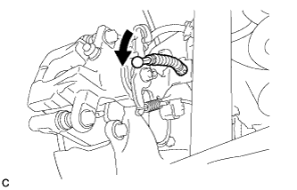 |
Separate the No. 3 parking brake cable assembly from the rear disc brake cylinder assembly.
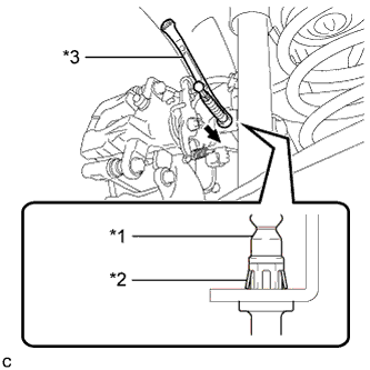 |
Separate the No. 3 parking brake cable assembly from the rear disc brake cylinder assembly.
| *1 | No. 3 Parking Brake Cable Assembly |
| *2 | Clip |
| *3 | Offset Wrench (14 mm) |
| 15. SEPARATE REAR FLEXIBLE HOSE |
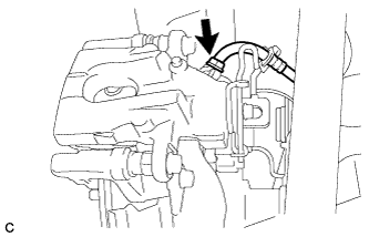 |
Remove the union bolt and gasket, and separate the rear flexible hose from the rear disc brake cylinder assembly.
| 16. REMOVE REAR DISC BRAKE CYLINDER ASSEMBLY |
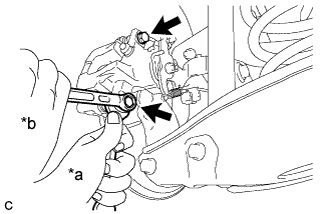 |
Hold the rear disc brake pad guide pin, and remove the 2 bolts and rear disc brake cylinder assembly.
| *a | Hold |
| *b | Turn |
| 17. REMOVE REAR DISC BRAKE PAD |
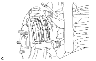 |
Remove the 2 anti-squeal springs from the rear disc brake pads.
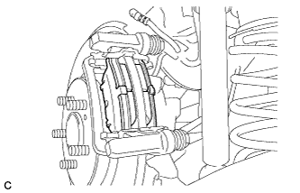 |
Remove the 2 rear disc brake pads from the disc brake cylinder mounting.
| 18. REMOVE REAR DISC BRAKE ANTI-SQUEAL SHIM |
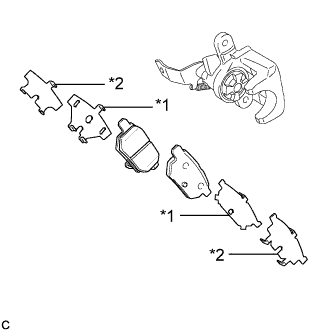 |
Remove the rear No. 1 disc brake anti-squeal shim and rear No. 2 disc brake anti-squeal shim from each rear disc brake pad.
| *1 | Rear No. 1 Disc Brake Anti-squeal Shim |
| *2 | Rear No. 2 Disc Brake Anti-squeal Shim |
| 19. REMOVE REAR DISC BRAKE PAD SUPPORT PLATE |
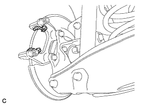 |
Remove the 2 rear disc brake pad support plates from the disc brake cylinder mounting.
| 20. REMOVE REAR DISC BRAKE PAD GUIDE PIN |
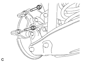 |
Remove the 2 rear disc brake pad guide pins from the disc brake cylinder mounting.
| 21. REMOVE REAR DISC BRAKE BUSHING DUST BOOT |
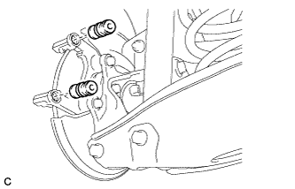 |
Remove the 2 rear disc brake bushing dust boots from the disc brake cylinder mounting.
| 22. REMOVE DISC BRAKE CYLINDER MOUNTING |
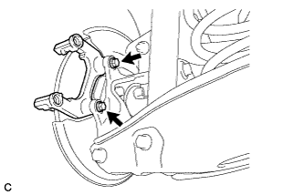 |
Remove the 2 bolts and disc brake cylinder mounting.
| 23. REMOVE REAR DISC |
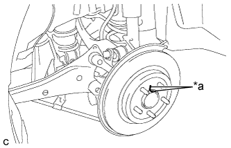 |
Put matchmarks on the disc and the axle hub.
| *a | Matchmark |
Remove the rear disc.
