FUEL INJECTOR > INSTALLATION |
| 1. INSTALL FUEL INJECTOR ASSEMBLY |
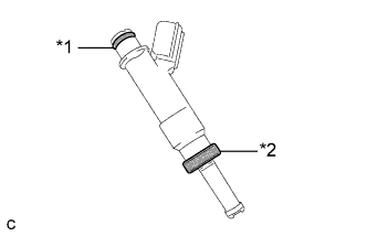 |
Install a new insulator and O-ring to each fuel injector assembly.
| *1 | O-ring |
| *2 | Insulator |
Apply a light coat of gasoline or spindle oil to the contact surfaces of the new O-ring on each fuel injector assembly.
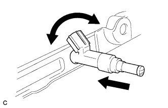 |
While turning the fuel injector assembly left and right, install it onto the fuel delivery pipe sub-assembly.
| 2. INSTALL NO. 1 DELIVERY PIPE SPACER |
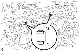 |
Install the 2 No. 1 delivery pipe spacers onto the cylinder head.
| *a | Delivery Pipe Side |
| *b | Cylinder Head Side |
| 3. INSTALL FUEL DELIVERY PIPE SUB-ASSEMBLY |
Install the fuel delivery pipe sub-assembly with the 4 fuel injector assemblies and install the 2 bolts.
Install the bolt to secure the fuel delivery pipe sub-assembly.
| 4. CONNECT FUEL TUBE SUB-ASSEMBLY |
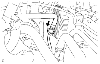 |
Push the tube connector into the pipe until the tube connector makes a "click" sound.
Engage the lock claw to install the No. 1 fuel pipe clamp.
| 5. CONNECT ENGINE WIRE |
Install the bolt.
Connect the 4 fuel injector connectors.
Connect the 4 connectors.
Attach the 2 clamps to connect the wire harness.
| 6. INSTALL EGR WITH COOLER PIPE SUB-ASSEMBLY |
| 7. CONNECT CABLE TO NEGATIVE AUXILIARY BATTERY TERMINAL |
| 8. INSPECT FOR FUEL LEAK |
Check fuel pump operation.
Connect the intelligent tester to the DLC3.
Turn the power switch on (IG).
Turn the intelligent tester on.
Enter the following menus: Powertrain / Engine and ECT / Active Test / Control the Fuel Pump / Speed.
Check for pressure in the fuel inlet tube from the fuel line. Check that sounds of fuel flowing from the fuel tank can be heard. If no sounds can be heard, check the integration relay, fuel pump, ECM and wiring connectors.
Inspect for fuel leaks.
Check that there are no fuel leaks after performing maintenance anywhere on the fuel system. If there are fuel leaks, repair or replace parts as necessary.
Turn the power switch off.
Disconnect the intelligent tester from the DLC3.
| 9. INSTALL REAR FLOOR BOARD UPPER NO. 3 PLATE |
Engage the 4 claws and 2 guides to install the rear floor board upper No. 3 plate.
| 10. INSTALL DECK FLOOR BOX RH |
Engage the 6 guides.
Install the deck floor box RH with the clip.
| 11. INSTALL REAR NO. 3 FLOOR BOARD |
Install the rear No. 3 floor board.
| 12. INSTALL REAR DECK FLOOR BOX |
Install the rear deck floor box.
| 13. INSTALL REAR NO. 2 FLOOR BOARD |
Install the rear No. 2 floor board.
