FUEL SYSTEM > PRECAUTION |
| 1.PRECAUTIONS |
Before inspecting and repairing the fuel system, disconnect the cable from the negative (-) auxiliary battery terminal.
Do not smoke or work near fire when handling the fuel system.
Keep gasoline away from rubber or leather parts.
| 2.DISCHARGE FUEL SYSTEM PRESSURE |
Remove the rear seat cushion assembly (Click here).
Disengage the claw and remove the 2 rear seat cushion lock hooks (Click here).
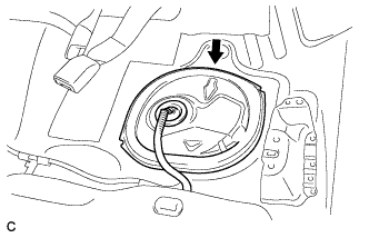 |
Remove the rear floor service hole cover.
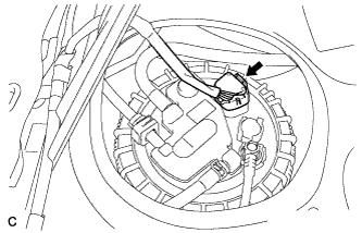 |
Disconnect the fuel pump connector.
Put the engine in inspection mode (Click here).
Start the engine.
After the engine has stopped on its own, turn the power switch off.
Crank the engine again and make sure that the engine does not start.
Disconnect the cable from the negative (-) auxiliary battery terminal.
Connect the fuel pump connector.
Loosen the fuel tank cap, then discharge the pressure in the fuel tank completely.
Install the rear floor service hole cover with new butyl tape.
Engage the claw to install the 2 new rear seat cushion lock hooks (Click here).
Install the rear seat cushion assembly (Click here).
| 3.FUEL LINE |
When disconnecting a high-pressure fuel line, a large amount of gasoline will spray out. Perform the following procedure:
Discharge the fuel system pressure.
Disconnect the fuel tube.
Drain the fuel remaining inside the fuel pump tube into a container.
Cover the disconnected pipe and connector with plastic bags to prevent damage and contamination.
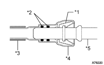 |
Perform the following procedure when disconnecting a fuel delivery pipe (metallic type):
| *1 | Retainer |
| *2 | O-ring |
| *3 | Nylon Tube |
| *4 | Housing |
| *5 | Pipe |
Check if there is any damage or foreign matter on the pipe connections.
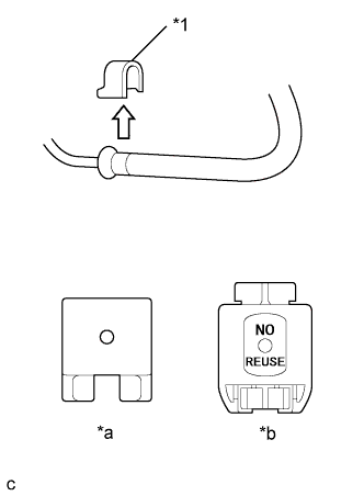 |
Remove the No. 2 fuel pipe clamp.
| *1 | No. 2 Fuel Pipe Clamp |
| *a | Type A |
| *b | Type B |
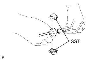 |
Assemble SST to the connector as shown in the illustration.
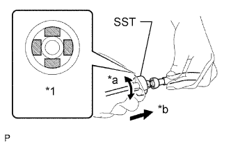 |
Turn SST, align the retainers inside the connector with the SST chamfers and insert SST into the connector.
| *1 | Retainer (4 places) |
| *a | Turn |
| *b | Push |
Slide SST and the connector together towards the fuel tube assembly.
Perform the following procedure when connecting a fuel tube connector (metallic type):
Check if there is any damage or foreign matter on the pipe connections.
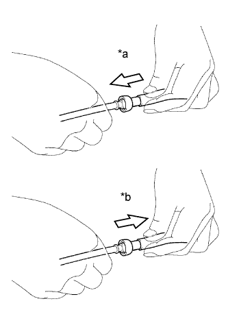 |
Match the axis of the connector with the axis of the pipe, and push the pipe into the connector until the connector makes a "click" sound. If it is difficult to push the pipe into the connector, apply a small amount of clean engine oil to the tip of the pipe.
| *a | Push |
| *b | Pull |
After connecting, check that the pipe and the connector are securely connected by pulling on them.
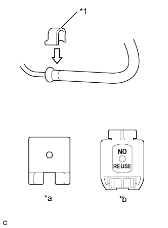 |
Install the No. 2 fuel pipe clamp. (Type A)
| *1 | No. 2 Fuel Pipe Clamp |
| *a | Type A |
| *b | Type B |
Install a new No. 2 fuel pipe clamp. (Type B)
Inspect for fuel leaks.
Perform the following procedure when disconnecting a fuel tube connector (quick type A):
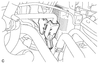 |
Release the claw and remove the No. 1 fuel pipe clamp.
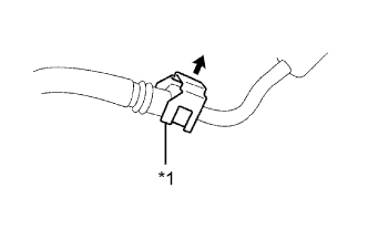 |
Disengage the lock claws by raising the fuel hose connector cover as shown in the illustration.
| *1 | Fuel Hose Connector Cover |
Check that there is no dirt or other foreign matter on the pipe and contact surface before disconnecting them. Clean them if necessary.
Disconnect the connector from the pipe by hand.
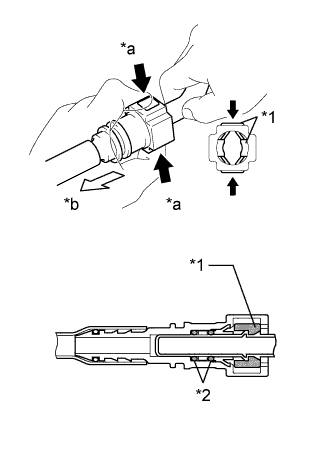 |
If the connector and the pipe are stuck, push in and pull on the connector to release them. Pull the connector out of the pipe carefully.
| *1 | Retainer |
| *2 | O-ring |
| *a | Pinch |
| *b | Pull Out |
Check that there is no dirt or other foreign matter on the contact surface of the disconnected pipe. Clean them away if necessary.
Cover the disconnected pipe and connector with plastic bags to prevent damage and contamination.
Perform the following procedure when connecting a fuel tube connector (quick type A):
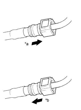 |
Check if there is any damage or foreign matter on the pipe connections.
| *a | Push |
| *b | Pull |
Match the axis of the connector with the axis of the pipe, and push the pipe into the connector until the connector makes a "click" sound. If it is difficult to push the pipe into the connector, apply a small amount of clean engine oil to the tip of the pipe.
After connecting, check that the pipe and connector are securely connected by pulling on them.
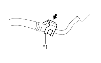 |
Engage the lock claws to the connector by pushing down on the fuel hose connector cover.
| *1 | Fuel Hose Connector Cover |
|
Engage the lock claw and install the No. 1 fuel pipe clamp.
Inspect for fuel leaks.
Perform the following procedure when disconnecting a fuel tube connector (quick type B):
Before disconnecting the connector, clean off any dirt that may be present.
Pull the tabs of the fuel tube retainer to disengage the 2 claws.
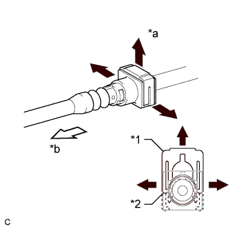 |
Pull the retainer up as shown in the illustration.
| *1 | Retainer |
| *2 | Claw |
| *a | Pinch |
| *b | Pull Out |
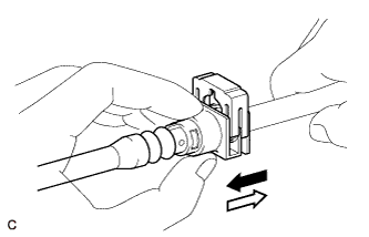 |
If the connector and pipe are stuck, hold the fuel pipe by hand and push and pull on the connector. Pull the two pipes apart to separate the connector.
If there is any dirt or any other foreign matter on the contact surfaces of the disconnected pipes, clean them as necessary.
Cover the disconnected pipe and connector with plastic bags to prevent damage and contamination.
Perform the following procedure when connecting a fuel tube connector (quick type B):
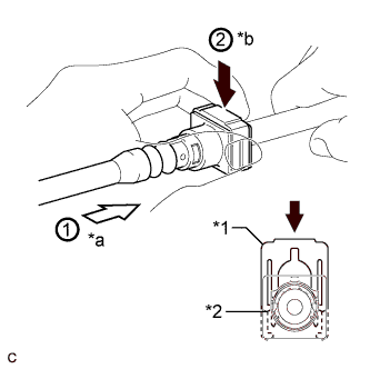 |
Line up the two parts of the pipes to be connected, and fully push the fuel tube connector and pipe together until they are fully seated. Next, push the retainer into the connector until its claws lock. If the pipe is difficult to push into the connector, apply a small amount of clean engine oil to the tip of the pipe and reinsert it.
| *1 | Retainer |
| *2 | Claw |
| *a | Push |
| *b | Push |
After connecting, check that the pipe and connector are securely connected by pulling on them.
Inspect for fuel leaks.
Perform the following procedure when disconnecting a fuel tube connector (quick type C).
Check if there is any dirt like mud on the pipe and around the connector before disconnecting them. Clean the dirt away if necessary.
Disconnect them by your hands.
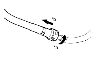 |
If the connector and the pipe are stuck, push in and pull on the connector to release them. Pull the connector out of the pipe carefully.
| *a | Push |
| *b | Pull |
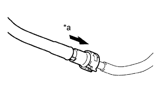
Inspect if there is any dirt or the like on the seal surface of the disconnected pipe. Clean it away if necessary.
Cover the disconnected pipe and connector with plastic bags to prevent damage and contamination.
 |
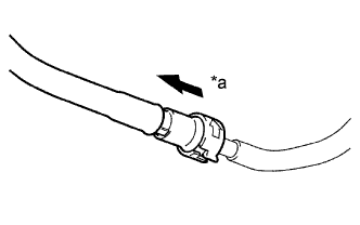
Perform the following procedure when connecting a fuel tube connector (quick type C).
| *a | Push |
Match the axis of the connector with the axis of the pipe, and push the pipe into the connector until the connector makes a "click" sound. If it is difficult to push the pipe into the connector, apply a small amount of clean engine oil to the tip of the pipe.
 |
After connecting, check that the pipe and the connector are securely connected by pulling on them.
| *a | Pull |
Inspect for fuel leak.
Observe the following precautions when handling a nylon tube.
Do not twist the connection part of the nylon tube and the quick connector when connecting them.
Do not bend, kink, or twist the nylon tube.
Do not remove the EPDM protector on the outside of the nylon tube.
Do not close the piping by kinking the nylon tube.
| 4.INJECTOR |
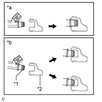 |
Observe the following precautions when removing and installing a fuel injector:
| *1 | O-ring |
| *2 | Delivery Pipe |
| *a | CORRECT |
| *b | INCORRECT |
Do not reuse the O-ring and insulator.
When placing a new O-ring onto the injector, do not damage the new O-ring.
Coat the new O-ring with grease or gasoline before installing it. Do not use engine oil, gear oil or brake fluid.
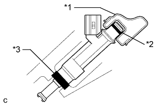 |
Install the injector into the delivery pipe and cylinder head as shown in the illustration. Apply grease or gasoline to the contact surfaces of the injector before installing the injector.
| *1 | Delivery Pipe |
| *2 | O-ring |
| *3 | Insulator |
| 5.FUEL SUCTION TUBE ASSEMBLY WITH PUMP AND GAUGE |
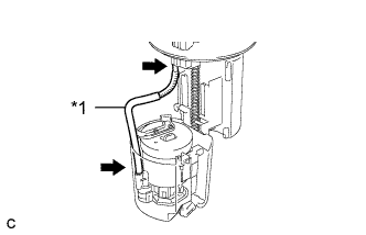 |
Do not disconnect the tube shown in the illustration when disassembling the fuel suction tube assembly with pump and gauge. Doing so will cause reassembly of the fuel suction tube assembly with pump and gauge to be impossible as the tube is welded to the plate.
| *1 | Tube |
| 6.INSPECT FOR FUEL LEAK |
Check that there are no fuel leaks after performing maintenance anywhere on the fuel system (Click here).
