CAN COMMUNICATION SYSTEM > Check CAN Bus Lines for Short Circuit (RHD Models) |
| Symptom | Trouble Area |
| Resistance between terminals 6 (CANH) and 14 (CANL) of DLC3 is below 54 Ω. |
|
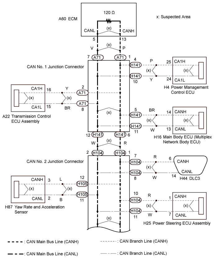
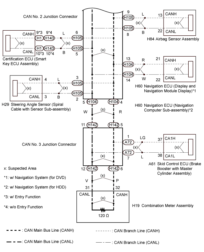
| 1.CHECK FOR SHORT IN CAN BUS LINES (ECM) |
Turn the power switch off.
 |
Disconnect the ECM connector.
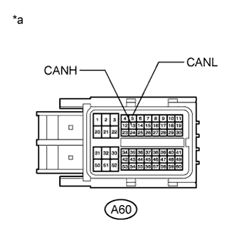
Measure the resistance according to the value(s) in the table below.
| Tester Connection | Switch Condition | Specified Condition |
| A60-13 (CANH) - A60-5 (CANL) | Power switch off | 108 to 132 Ω |
| *a | Front view of wire harness connector (to ECM) |
|
| ||||
| OK | ||
 | ||
| ||
| 2.CHECK FOR SHORT IN CAN BUS LINES (COMBINATION METER ASSEMBLY) |
Reconnect the ECM connector.
 |
Disconnect the combination meter assembly connector.
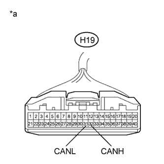
Measure the resistance according to the value(s) in the table below.
| Tester Connection | Switch Condition | Specified Condition |
| H19-32 (CANH) - H19-31 (CANL) | Power switch off | 108 to 132 Ω |
| *a | Front view of wire harness connector (to Combination Meter Assembly) |
|
| ||||
| OK | ||
| ||
| ||
| 3.CHECK FOR SHORT IN CAN BUS LINES (CAN NO. 2 J/C) |
Reconnect the combination meter assembly connector.
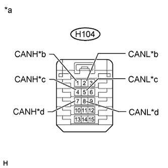 |
Disconnect the wire harness connector from the CAN No. 2 junction connector rear side.
Measure the resistance according to the value(s) in the table below.
| Tester Connection | Switch Condition | Specified Condition | Connected to |
| H104-1 (CANH) - H104-2 (CANL) | Power switch off | 108 to 132 Ω | CAN No. 1 junction connector |
| H104-4 (CANH) - H104-5 (CANL) | Power switch off | 108 to 132 Ω | CAN No. 3 junction connector |
| H104-7 (CANH) - H104-8 (CANL) | Power switch off | 1 MΩ or higher | DLC3 |
| *a | Front view of wire harness connector (to CAN No. 2 Junction Connector) |
| *b | to CAN No. 1 Junction Connector |
| *c | to CAN No. 3 Junction Connector |
| *d | to DLC3 |
| Result | Proceed to |
| OK | A |
| NG (CAN No. 1 J/C main line) | B |
| NG (CAN No. 3 J/C main line) | C |
| NG (DLC3 branch line) | D |
|
| ||||
|
| ||||
|
| ||||
| A | |
 |
| 4.CHECK FOR SHORT IN CAN BUS LINES (CAN NO. 2 J/C - POWER STEERING ECU ASSEMBLY) |
Disconnect the power steering ECU assembly connector.
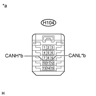 |
Measure the resistance according to the value(s) in the table below.
| Tester Connection | Switch Condition | Specified Condition |
| H104-10 (CANH) - H104-11 (CANL) | Power switch off | 1 MΩ or higher |
| *a | Front view of wire harness connector (to CAN No. 2 Junction Connector) |
| *b | to Power Steering ECU Assembly |
|
| ||||
| OK | |
|
| 5.CHECK FOR SHORT IN CAN BUS LINES (CAN NO. 2 J/C - NAVIGATION ECU) |
Disconnect the navigation ECU connector.
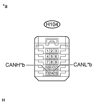 |
Measure the resistance according to the value(s) in the table below.
| Tester Connection | Switch Condition | Specified Condition |
| H104-13 (CANH) - H104-14 (CANL) | Power switch off | 1 MΩ or higher |
| *a | Front view of wire harness connector (to CAN No. 2 Junction Connector) |
| *b | to Navigation ECU |
|
| ||||
| OK | |
|
| 6.CHECK FOR SHORT IN CAN BUS LINES (CAN NO. 2 J/C - YAW RATE AND ACCELERATION SENSOR) |
Disconnect the CAN No. 2 junction connector front side.
Disconnect the yaw rate and acceleration sensor connector.
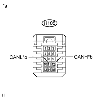 |
Measure the resistance according to the value(s) in the table below.
| Tester Connection | Switch Condition | Specified Condition |
| H105-12 (CANH) - H105-11 (CANL) | Power switch off | 1 MΩ or higher |
| *a | Front view of wire harness connector (to CAN No. 2 Junction Connector) |
| *b | to Yaw Rate and Acceleration Sensor |
|
| ||||
| OK | |
|
| 7.CHECK FOR SHORT IN CAN BUS LINES (CAN NO. 2 J/C - STEERING ANGLE SENSOR) |
Disconnect the steering angle sensor connector.
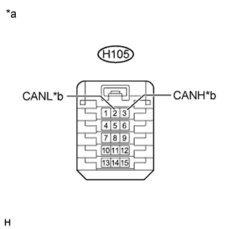 |
Measure the resistance according to the value(s) in the table below.
| Tester Connection | Switch Condition | Specified Condition |
| H105-3 (CANH) - H105-2 (CANL) | Power switch off | 1 MΩ or higher |
| *a | Front view of wire harness connector (to CAN No. 2 Junction Connector) |
| *b | to Steering Angle Sensor |
|
| ||||
| OK | |
|
| 8.CHECK FOR SHORT IN CAN BUS LINES (CAN NO. 2 J/C - AIRBAG SENSOR ASSEMBLY) |
Disconnect the airbag sensor assembly connector.
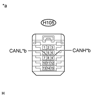 |
Measure the resistance according to the value(s) in the table below.
| Tester Connection | Switch Condition | Specified Condition |
| H105-9 (CANH) - H105-8 (CANL) | Power switch off | 1 MΩ or higher |
| *a | Front view of wire harness connector (to CAN No. 2 Junction Connector) |
| *b | to Airbag Sensor Assembly |
|
| ||||
| OK | |
|
| 9.CHECK FOR SHORT IN CAN BUS LINES (CAN NO. 2 J/C - CERTIFICATION ECU) |
Disconnect the certification ECU (smart key ECU assembly) connector.
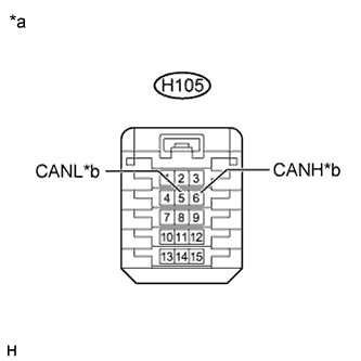 |
Measure the resistance according to the value(s) in the table below.
| Tester Connection | Switch Condition | Specified Condition |
| H105-6 (CANH) - H105-5 (CANL) | Power switch off | 1 MΩ or higher |
| *a | Front view of wire harness connector (to CAN No. 2 Junction Connector) |
| *b | to Certification ECU (Smart Key ECU Assembly) |
|
| ||||
| OK | |
|
| 10.CHECK FOR SHORT IN CAN BUS LINES (CAN NO. 2 J/C) |
Reconnect the wire harness connector to the CAN No. 2 junction connector front side and rear side.
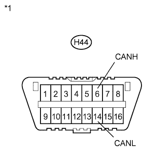 |
Measure the resistance according to the value(s) in the table below.
| Tester Connection | Switch Condition | Specified Condition |
| H44-6 (CANH) - H44-14 (CANL) | Power switch off | 54 to 69 Ω |
| *1 | DLC3 |
|
| ||||
| OK | |
|
| Go to step 12 |
| 11.CHECK FOR SHORT IN CONNECTED COMPONENT (ECU, SENSOR) |
|
Connect the probes of an ohmmeter to terminals 6 (CANH) and 14 (CANL) of the DLC3.
| *1 | DLC3 |
While observing the resistance value shown on the ohmmeter, reconnect each ECU and sensor connector until the resistance becomes abnormal (Below 54 Ω).
| NEXT | ||
| ||
| ||
| 12.CHECK FOR SHORT IN CAN BUS LINES (CAN NO. 2 J/C - CAN NO. 1 J/C) |
Reconnect the wire harness connector to the CAN No. 2 junction connector rear side.
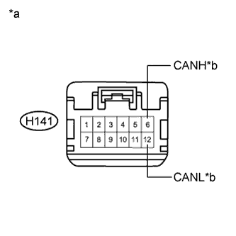 |
Disconnect the instrument panel wire from the CAN No. 1 junction connector.
Measure the resistance according to the value(s) in the table below.
| Tester Connection | Switch Condition | Specified Condition |
| H141-6 (CANH) - H141-12 (CANL) | Power switch off | 108 to 132 Ω |
| *a | Front view of wire harness connector (to CAN No. 1 Junction Connector) |
| *b | to CAN No. 2 Junction Connector |
|
| ||||
| OK | |
|
| 13.CHECK FOR SHORT IN CAN BUS LINES (CAN NO. 1 J/C - MAIN BODY ECU) |
Disconnect the main body ECU (multiplex network body ECU) connector.
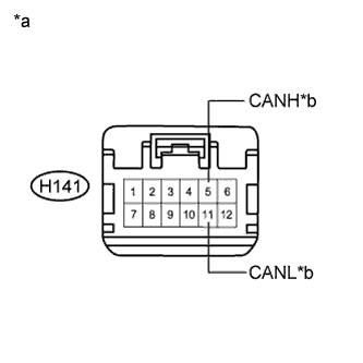 |
Measure the resistance according to the value(s) in the table below.
| Tester Connection | Switch Condition | Specified Condition |
| H141-5 (CANH) - H141-11 (CANL) | Power switch off | 1 MΩ or higher |
| *a | Front view of wire harness connector (to CAN No. 1 Junction Connector) |
| *b | to Main Body ECU |
|
| ||||
| OK | |
|
| 14.CHECK FOR SHORT IN CAN BUS LINES (CAN NO. 1 J/C - TRANSMISSION CONTROL ECU ASSEMBLY) |
Disconnect the transmission control ECU assembly connector.
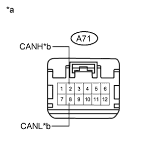 |
Disconnect the engine room main wire from the CAN No. 1 junction connector.
Measure the resistance according to the value(s) in the table below.
| Tester Connection | Switch Condition | Specified Condition |
| A71-2 (CANH) - A71-8 (CANL) | Power switch off | 1 MΩ or higher |
| *a | Front view of wire harness connector (to CAN No. 1 Junction Connector) |
| *b | to Transmission Control ECU Assembly |
|
| ||||
| OK | |
|
| 15.CHECK FOR SHORT IN CAN BUS LINES (CAN NO. 1 J/C - POWER MANAGEMENT CONTROL ECU) |
Disconnect the power management control ECU connector.
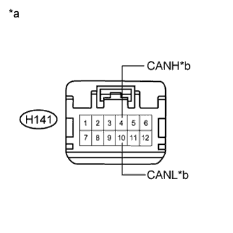 |
Measure the resistance according to the value(s) in the table below.
| Tester Connection | Switch Condition | Specified Condition |
| H141-4 (CANH) - H141-10 (CANL) | Power switch off | 1 MΩ or higher |
| *a | Front view of wire harness connector (to CAN No. 1 Junction Connector) |
| *b | to Power Management Control ECU |
|
| ||||
| OK | |
|
| 16.CHECK FOR SHORT IN CAN BUS LINES (CAN NO. 1 J/C - ECM) |
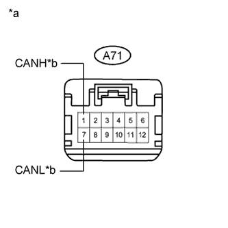 |
Measure the resistance according to the value(s) in the table below.
| Tester Connection | Switch Condition | Specified Condition |
| A71-1 (CANH) - A71-7 (CANL) | Power switch off | 108 to 132 Ω |
| *a | Front view of wire harness connector (to CAN No. 1 Junction Connector) |
| *b | to ECM |
|
| ||||
| OK | |
|
| 17.CHECK FOR SHORT IN CAN BUS LINES (CAN NO. 1 J/C) |
Reconnect the instrument panel wire and engine room main wire to the CAN No. 1 junction connector.
|
Measure the resistance according to the value(s) in the table below.
| Tester Connection | Switch Condition | Specified Condition |
| H44-6 (CANH) - H44-14 (CANL) | Power switch off | 54 to 69 Ω |
| *1 | DLC3 |
|
| ||||
| OK | |
|
| 18.CHECK FOR SHORT IN CAN BUS LINES (ECU, SENSOR) |
|
Connect the probes of an ohmmeter to terminals 6 (CANH) and 14 (CANL) of the DLC3.
| *1 | DLC3 |
While observing the resistance value shown on the ohmmeter, reconnect each ECU and sensor connector until the resistance becomes abnormal (Below 54 Ω).
| NEXT | ||
| ||
| ||
| 19.CHECK FOR SHORT IN CAN BUS LINES (CAN NO. 3 J/C - CAN NO. 2 J/C) |
Reconnect the wire harness connector to the CAN No. 2 junction connector rear side.
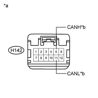 |
Disconnect the instrument panel wire from the CAN No. 3 junction connector.
Measure the resistance according to the value(s) in the table below.
| Tester Connection | Switch Condition | Specified Condition | Connected to |
| H142-5 (CANH) - H142-11 (CANL) | Power switch off | 108 to 132 Ω | CAN No. 2 junction connector |
| *a | Front view of wire harness connector (to CAN No. 3 Junction Connector) |
| *b | to CAN No. 2 Junction Connector |
|
| ||||
| OK | |
|
| 20.CHECK FOR SHORT IN CAN BUS LINES (CAN NO. 3 J/C - COMBINATION METER ASSEMBLY) |
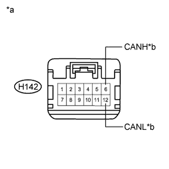 |
Measure the resistance according to the value(s) in the table below.
| Tester Connection | Switch Condition | Specified Condition | Connected to |
| H142-6 (CANH) - H142-12 (CANL) | Power switch off | 108 to 132 Ω | Combination meter assembly |
| *a | Front view of wire harness connector (to CAN No. 3 Junction Connector) |
| *b | to Combination Meter Assembly |
|
| ||||
| OK | |
|
| 21.CHECK FOR SHORT IN CAN BUS LINES (CAN NO. 3 J/C - SKID CONTROL ECU) |
Disconnect the engine room main wire from the CAN No. 3 junction connector.
Disconnect the skid control ECU (brake booster with master cylinder assembly) connector.
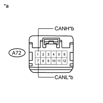 |
Measure the resistance according to the value(s) in the table below.
| Tester Connection | Switch Condition | Specified Condition |
| A72-1 (CANH) - A72-7 (CANL) | Power switch off | 1 MΩ or higher |
| *a | Front view of wire harness connector (to CAN No. 3 Junction Connector) |
| *b | to Skid Control ECU |
|
| ||||
| OK | |
|
| 22.CHECK FOR SHORT IN CAN BUS LINES (CAN NO. 3 J/C) |
Reconnect the instrument panel wire and engine room main wire to the CAN No. 3 junction connector.
|
Measure the resistance according to the value(s) in the table below.
| Tester Connection | Switch Condition | Specified Condition |
| H44-6 (CANH) - H44-14 (CANL) | Power switch off | 54 to 69 Ω |
| *1 | DLC3 |
|
| ||||
| OK | |
|
| 23.CHECK FOR SHORT IN CAN BUS LINES (ECU, SENSOR) |
|
Connect the probes of an ohmmeter to terminals 6 (CANH) and 14 (CANL) of the DLC3.
| *1 | DLC3 |
While observing the resistance value shown on the ohmmeter, reconnect each ECU and sensor connector until the resistance becomes abnormal (Below 54 Ω).
| NEXT | ||
| ||
| ||


