CAN COMMUNICATION SYSTEM > Check CAN Bus Line for Short to GND (LHD Models) |
| Symptom | Trouble Area |
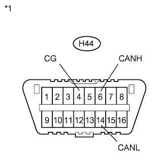
| No resistance exists between terminals 6 (CANH) and 4 (CG) or 14 (CANL) and 4 (CG) of DLC3. |
|
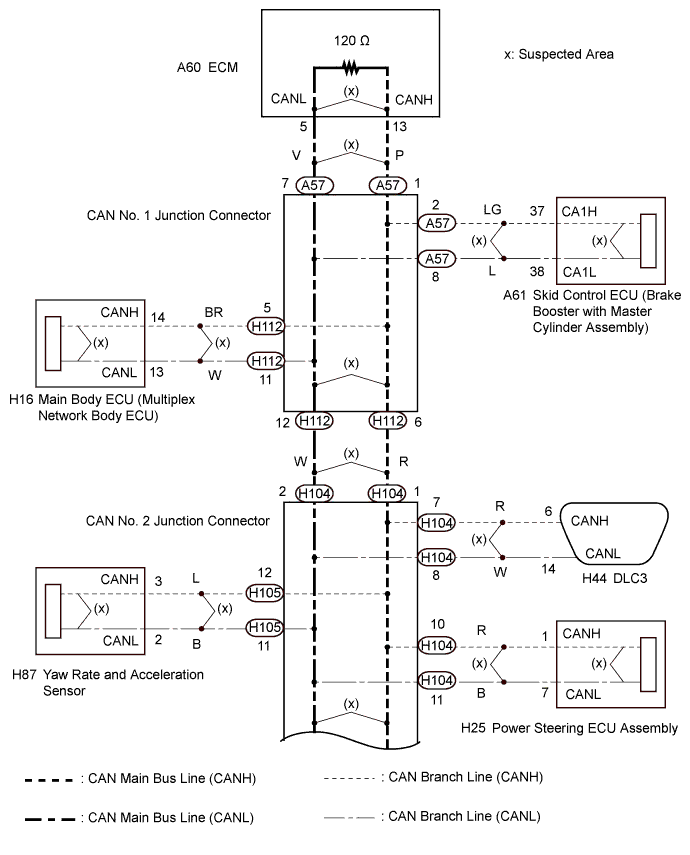
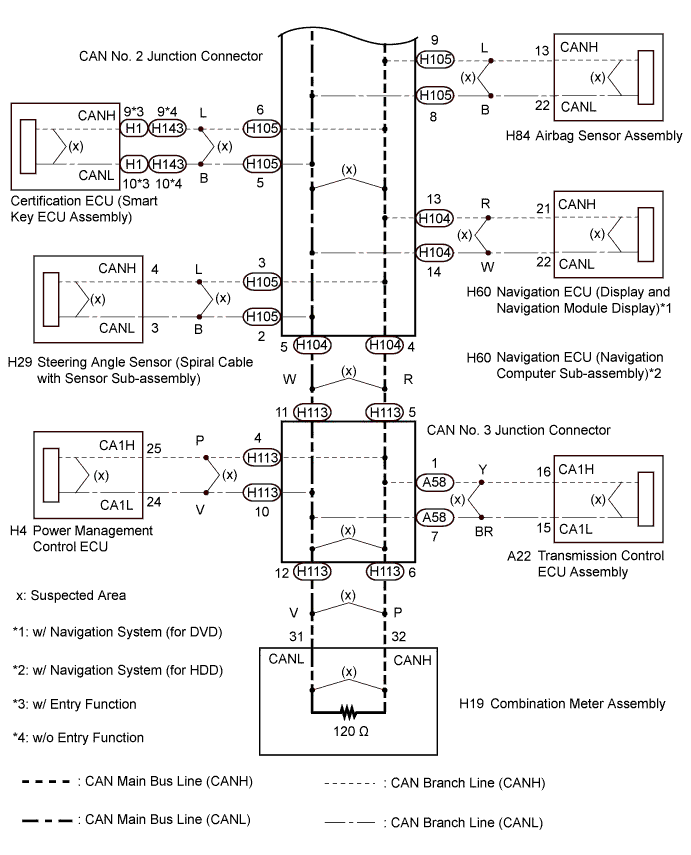
| 1.CHECK FOR SHORT TO GND IN CAN BUS LINE (CAN NO. 2 J/C) |
Turn the power switch off.
 |
Disconnect the wire harness connector from the CAN No. 2 junction connector rear side.
Measure the resistance according to the value(s) in the table below.
| Tester Connection | Switch Condition | Specified Condition | Connected to |
| H104-1 (CANH) - H44-4 (CG) | Power switch off | 200 Ω or higher | CAN No. 1 junction connector |
| H104-2 (CANL) - H44-4 (CG) | |||
| H104-4 (CANH) - H44-4 (CG) | Power switch off | 200 Ω or higher | CAN No. 3 junction connector |
| H104-5 (CANL) - H44-4 (CG) | |||
| H104-7 (CANH) - H44-4 (CG) | Power switch off | 200 Ω or higher | DLC3 |
| H104-8 (CANL) - H44-4 (CG) | |||
| H104-10 (CANH) - H44-4 (CG) | Power switch off | 200 Ω or higher | Power steering ECU assembly |
| H104-11 (CANL) - H44-4 (CG) | |||
| H104-13 (CANH) - H44-4 (CG) | Power switch off | 200 Ω or higher | Navigation ECU |
| H104-14 (CANL) - H44-4 (CG) |
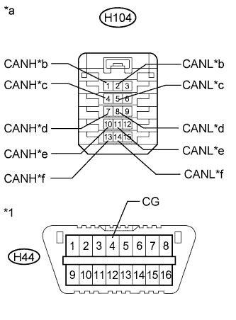
| *1 | DLC3 |
| *a | Front view of wire harness connector (to CAN No. 2 Junction Connector) |
| *b | to CAN No. 1 Junction Connector |
| *c | to CAN No. 3 Junction Connector |
| *d | to DLC3 |
| *e | to Power Steering ECU Assembly |
| *f | to Navigation ECU |
| Result | Proceed to |
| OK | A |
| NG (DLC3 branch line) | B |
| NG (CAN No. 1 junction connector main line) | C |
| NG (CAN No. 3 junction connector main line) | D |
| NG (ECU or sensor wire) | E |
|
| ||||
|
| ||||
|
| ||||
|
| ||||
| A | |
 |
| 2.CHECK FOR SHORT TO GND IN CAN BUS LINE (CAN NO. 2 J/C) |
 |
Disconnect the wire harness connector from the CAN No. 2 junction connector front side.
Measure the resistance according to the value(s) in the table below.
| Tester Connection | Switch Condition | Specified Condition | Connected to |
| H105-3 (CANH) - H44-4 (CG) | Power switch off | 200 Ω or higher | Steering angle sensor (Spiral cable with sensor sub-assembly) |
| H105-2 (CANL) - H44-4 (CG) | |||
| H105-6 (CANH) - H44-4 (CG) | Power switch off | 200 Ω or higher | Certification ECU (Smart key ECU assembly) |
| H105-5 (CANL) - H44-4 (CG) | |||
| H105-9 (CANH) - H44-4 (CG) | Power switch off | 200 Ω or higher | Airbag sensor assembly |
| H105-8 (CANL) - H44-4 (CG) | |||
| H105-12 (CANH) - H44-4 (CG) | Power switch off | 200 Ω or higher | Yaw rate and acceleration sensor |
| H105-11 (CANL) - H44-4 (CG) |
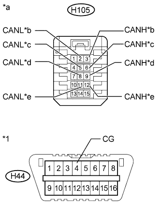
| *1 | DLC3 |
| *a | Front view of wire harness connector (to CAN No. 2 Junction Connector) |
| *b | to Steering Angle Sensor (Spiral Cable with Sensor Sub-assembly) |
| *c | to Certification ECU (Smart Key ECU Assembly) |
| *d | to Airbag Sensor Assembly |
| *e | to Yaw Rate and Acceleration Sensor |
| Result | Proceed to |
| OK | A |
| NG (ECU or sensor wire) | B |
|
| ||||
| A | ||
 | ||
| ||
| 3.CHECK FOR SHORT TO GND IN CAN BUS LINE (CAN NO. 1 J/C) |
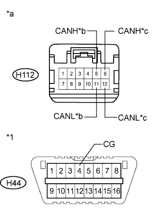 |
Disconnect the instrument panel wire from the CAN No. 1 junction connector.
Measure the resistance according to the value(s) in the table below.
| Tester Connection | Switch Condition | Specified Condition | Connected to |
| H112-5 (CANH) - H44-4 (CG) | Power switch off | 200 Ω or higher | Main body ECU (Multiplex network body ECU) |
| H112-11 (CANL) - H44-4 (CG) | |||
| H112-6 (CANH) - H44-4 (CG) | Power switch off | 200 Ω or higher | CAN No. 2 junction connector |
| H112-12 (CANL) - H44-4 (CG) |
| *1 | DLC3 |
| *a | Front view of wire harness connector (to CAN No. 1 Junction Connector) |
| *b | to Main Body ECU (Multiplex Network Body ECU) |
| *c | to CAN No. 2 Junction Connector |
| Result | Proceed to |
| OK | A |
| NG (CAN No. 2 junction connector main line) | B |
| NG (Main body ECU branch line) | C |
|
| ||||
|
| ||||
| A | |
|
| 4.CHECK SHORT TO GND IN CAN BUS LINE (CAN NO. 1 J/C) |
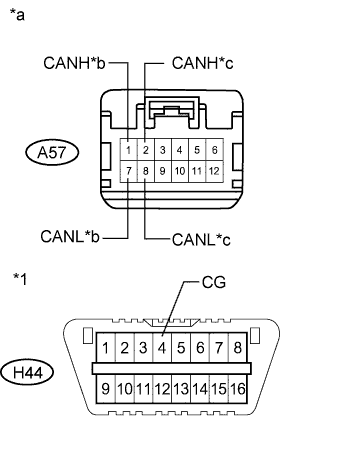 |
Disconnect the engine room main wire from the CAN No. 1 junction connector.
Measure the resistance according to the value(s) in the table below.
| Tester Connection | Switch Condition | Specified Condition | Connected to |
| A57-1 (CANH) - H44-4 (CG) | Power switch off | 200 Ω or higher | ECM |
| A57-7 (CANL) - H44-4 (CG) | |||
| A57-2 (CANH) - H44-4 (CG) | Power switch off | 200 Ω or higher | Skid Control ECU (Brake Booster with Master Cylinder Assembly) |
| A57-8 (CANL) - H44-4 (CG) |
| *1 | DLC3 |
| *a | Front view of wire harness connector (to CAN No. 2 Junction Connector) |
| *b | to ECM |
| *c | to Skid Control ECU |
| Result | Proceed to |
| OK | A |
| NG (ECU or sensor wire) | B |
|
| ||||
| A | ||
| ||
| ||
| 5.CHECK SHORT TO GND IN CAN BUS LINE (CAN NO. 3 J/C) |
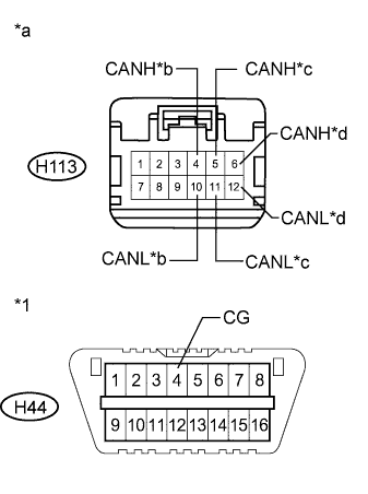 |
Disconnect the instrument panel wire from the CAN No. 3 junction connector.
Measure the resistance according to the value(s) in the table below.
| Tester Connection | Switch Condition | Specified Condition | Connected to |
| H113-4 (CANH) - H44-4 (CG) | Power switch off | 200 Ω or higher | Power management control ECU |
| H113-10 (CANL) - H44-4 (CG) | |||
| H113-5 (CANH) - H44-4 (CG) | Power switch off | 200 Ω or higher | CAN No. 2 junction connector |
| H113-11 (CANL) - H44-4 (CG) | |||
| H113-6 (CANH) - H44-4 (CG) | Power switch off | 200 Ω or higher | Combination meter assembly |
| H113-12 (CANL) - H44-4 (CG) |
| *1 | DLC3 |
| *a | Front view of wire harness connector (to CAN No. 3 Junction Connector) |
| *b | to Power Management Control ECU |
| *c | to CAN No. 2 Junction Connector |
| *d | to Combination Meter Assembly |
| Result | Proceed to |
| OK | A |
| NG (CAN No. 2 junction connector main line) | B |
| NG (ECU or sensor wire) | C |
|
| ||||
|
| ||||
| A | |
|
| 6.CHECK SHORT TO GND IN CAN BUS LINE (CAN NO. 3 J/C) |
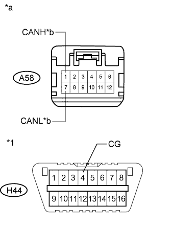 |
Disconnect the engine room main wire from the CAN No. 3 junction connector.
Measure the resistance according to the value(s) in the table below.
| Tester Connection | Switch Condition | Specified Condition | Connected to |
| A58-1 (CANH) - H44-4 (CG) | Power switch off | 200 Ω or higher | Transmission control ECU |
| A58-7 (CANL) - H44-4 (CG) |
| *1 | DLC3 |
| *a | Front view of wire harness connector (to CAN No. 3 Junction Connector) |
| *b | to Transmission Control ECU Assembly |
| Result | Proceed to |
| OK | A |
| NG (Transmission control ECU assembly branch line) | B |
|
| ||||
| A | ||
| ||
| ||
| 7.CHECK FOR SHORT TO GND IN CONNECTED COMPONENT (ECU, SENSOR) |
Reconnect all wire harness connectors (CAN J/C1, CAN J/C2 and CAN J/C3).
Disconnect the ECU or sensor connected to the CAN bus line that is shorted to ground.
 |
Measure the resistance according to the value(s) in the table below.
| Tester Connection | Switch Condition | Specified Condition |
| H44-6 (CANH) - H44-4 (CG) | Power switch off | 200 Ω or higher |
| H44-14 (CANL) - H44-4 (CG) |
| *1 | DLC3 |
|
| ||||
| OK | ||
| ||
| ||


