FRONT DRIVE SHAFT ASSEMBLY > INSTALLATION

for Preparation Click here


1. INSTALL FRONT DRIVE SHAFT HOLE SNAP RING
  1. Install a new front drive shaft hole snap ring to the front drive inboard joint assembly.

    NOTICE:
    Face the end gap of the front drive inboard joint hole snap ring downward.


2. INSTALL FRONT DRIVE SHAFT ASSEMBLY


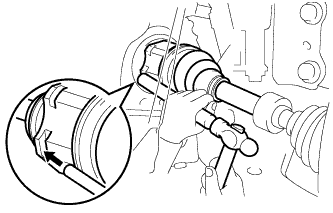
    C208486
  1. Align the inboard joint splines, and using a brass bar and a hammer, install the front drive shaft assembly.
    NOTICE:
    1. Face the end gap of the front drive shaft hole snap ring downward.
    2. Do not damage the transaxle case oil seal.
    3. Do not damage the inboard joint boot.
    4. Make sure to center the front drive shaft assembly during installation to prevent damage to the front drive shaft hole snap ring.

    HINT:
    Confirm whether the drive shaft is securely driven in by checking the reaction force and sound.


    C208473E02
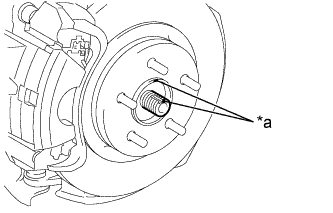
  1. Align the matchmarks and install the front drive shaft assembly to the front axle hub sub-assembly.
    Text in Illustration 
    *a
    Matchmark


3. CONNECT FRONT LOWER NO. 1 SUSPENSION ARM SUB-ASSEMBLY
  1. Install the front lower No. 1 suspension arm sub-assembly to the front lower ball joint assembly with the bolt and 2 nuts.

    Torque:
    89 N*m{ 908 kgf*cm , 66 ft.*lbf }


4. INSTALL FRONT STABILIZER LINK ASSEMBLY
  1. Install the front stabilizer link assembly to the front shock absorber with coil spring with the nut.

    Torque:
    74 N*m{ 755 kgf*cm , 55 ft.*lbf }

    HINT:
    If the ball joint turns together with the nut, use a hexagon wrench (6 mm) to hold the stud bolt.


5. CONNECT TIE ROD END SUB-ASSEMBLY


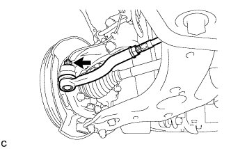
    C151407
  1. Connect the tie rod end sub-assembly LH to the steering knuckle with the nut.

    Torque:
    49 N*m{ 500 kgf*cm , 36 ft.*lbf }

    NOTICE:
    Further tighten the nut up to 60° if the holes for the clip are not aligned.

  1. Install a new clip.


6. INSTALL FRONT FLEXIBLE HOSE
  1. Install the front flexible hose to the steering knuckle with the bolt.

    Torque:
    19 N*m{ 192 kgf*cm , 14 ft.*lbf }


7. INSTALL FRONT SPEED SENSOR
  1. Install the front speed sensor and front flexible hose to the front shock absorber with the bolt and clamp.

    Torque:
    19 N*m{ 192 kgf*cm , 14 ft.*lbf }

    NOTICE:
    Do not twist the front speed sensor when installing it.

    HINT:
    Install the front flexible hose first and then the speed sensor harness bracket.

  1. Install the front speed sensor to the steering knuckle with the bolt.

    Torque:
    8.5 N*m{ 87 kgf*cm , 75 in.*lbf }

    NOTICE:
    Do not twist the front speed sensor when installing it.


8. INSTALL FRONT AXLE SHAFT NUT
  1. Clean the threaded parts on the front drive shaft assembly and a new front axle shaft nut using a non-residue solvent.
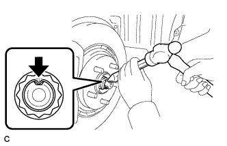
    HINT:
    1. Be sure to perform this work even when using a new drive shaft.
    2. Keep the threaded parts free of oil and foreign matter.


    C210914
  1. Using a socket wrench (30 mm), install the axle shaft nut.

    Torque:
    216 N*m{ 2203 kgf*cm , 159 ft.*lbf }

  1. Using a chisel and hammer, stake the front axle shaft nut.


9. ADD HYBRID TRANSAXLE FLUID


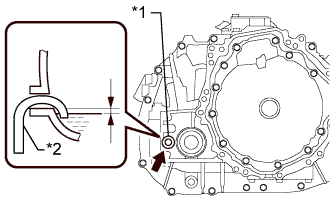
    C233704E01
  1. Add transaxle fluid until the fluid level is between 0 to 10 mm (0 to 0.394 in.) from the bottom lip of the filler plug opening.
    Text in Illustration 
    *1
    Filler Plug
    *2
    Filler Nozzle

    NOTICE:
    1. Stop the vehicle on a level surface.
    2. Use Toyota Genuine ATF WS.
    3. Be sure to fully insert the filler nozzle into the filler plug opening.
    4. Be sure to add fluid slowly. If fluid is added quickly, the fluid may hit internal parts and bounce back, resulting in fluid coming out of the filler plug opening.
    5. Be sure to directly check that the transaxle fluid level is within the specified range.
    6. Insufficient or excessive amounts of transaxle fluid may damage the hybrid transaxle.

    Reference:
    3.4 liters (3.6 US qts, 3.0 lmp.qts)

  1. After adding fluid, leave it for 30 seconds so that the fluid surface can become still again, and then check that the fluid level is between 0 to 10 mm (0 to 0.394 in.) from the bottom lip of the filler plug opening. (If the fluid level is too low, return to the Add Hybrid Transaxle Fluid procedure.)

    NOTICE:
    After adding fluid, make sure to check the fluid level.


10. INSPECT HYBRID TRANSAXLE FLUID


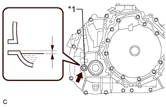
    C209290E01
  1. Using a 10 mm hexagon socket wrench, remove the filler plug and gasket.
    Text in Illustration 
    *1
    Filler Plug

  1. Check that the fluid level is between 0 to 10 mm (0 to 0.394 in.) from the bottom lip of the filler plug opening. (If the fluid level is too low, return to the Add Hybrid Transaxle Fluid procedure.)

    NOTICE:
    1. Stop the vehicle on a level surface.
    2. Be sure to directly check that the transaxle fluid level is within the specified range.
    3. Insufficient or excessive amounts of transaxle fluid may damage the hybrid transaxle.
    4. If the fluid was replaced or fluid was added, make sure to recheck the fluid level after driving the vehicle.

  1. Check for leaks if the quantity of transaxle fluid is low.

  1. Using a 10 mm hexagon socket wrench, install the filler plug with a new gasket.

    Torque:
    39 N*m{ 398 kgf*cm , 29 ft.*lbf }


11. INSPECT FOR TRANSAXLE FLUID LEAK


12. INSTALL FRONT WHEELS

Torque:
103 N*m{ 1050 kgf*cm , 76 ft.*lbf }


13. INSPECT AND ADJUST FRONT WHEEL ALIGNMENT
(Click here)


14. INSTALL REAR ENGINE UNDER COVER LH


15. INSTALL REAR ENGINE UNDER COVER RH


16. INSTALL NO. 1 ENGINE UNDER COVER


17. INSPECT SPEED SENSOR SIGNAL
(Click here)