FRONT DRIVE SHAFT ASSEMBLY > REMOVAL |
| 1. REMOVE FRONT WHEELS |
| 2. REMOVE NO. 1 ENGINE UNDER COVER |
| 3. REMOVE REAR ENGINE UNDER COVER LH |
| 4. REMOVE REAR ENGINE UNDER COVER RH |
| 5. DRAIN HYBRID TRANSAXLE FLUID |
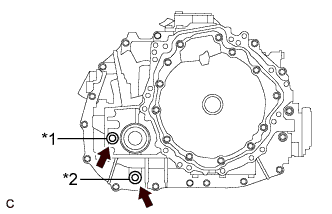 |
Using a 10 mm hexagon socket wrench, remove the filler plug and gasket.
| *1 | Filler Plug |
| *2 | Drain Plug |
Using a 10 mm hexagon socket wrench, remove the drain plug and gasket.
Using a 10 mm hexagon socket wrench, install the drain plug and a new gasket.
| 6. REMOVE FRONT AXLE SHAFT NUT |
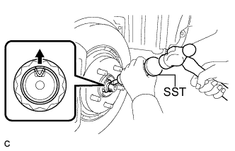 |
Using SST and a hammer, release the staked part of the front axle shaft nut.
While applying the brakes, remove the front axle shaft nut.
| 7. SEPARATE FRONT SPEED SENSOR |
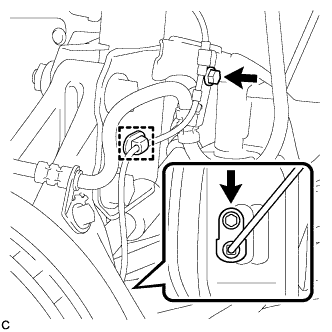 |
Remove the 2 bolts and disengage the clamp, and separate the front speed sensor.
| 8. SEPARATE FRONT FLEXIBLE HOSE |
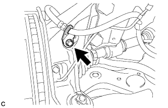 |
Remove the bolt and separate the front flexible hose from the steering knuckle.
| 9. SEPARATE TIE ROD END SUB-ASSEMBLY |
Remove the clip and nut.
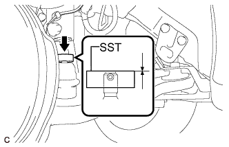 |
Install SST to the tie rod end.
Secure SST using a string.
Using SST, separate the tie rod end from the steering knuckle.
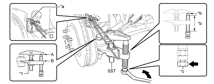
| *1 | Center Nut | - | - |
| *a | String | *b | Grease Application Area |
| *c | Place the wrench here. | - | - |
| 10. SEPARATE FRONT STABILIZER LINK ASSEMBLY |
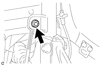 |
Remove the nut and separate the front stabilizer link assembly from the front shock absorber with coil spring.
| 11. SEPARATE FRONT LOWER NO. 1 SUSPENSION ARM SUB-ASSEMBLY |
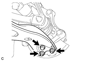 |
Remove the bolt and 2 nuts, and separate the front lower No. 1 suspension arm sub-assembly from the front lower ball joint assembly.
| 12. SEPARATE FRONT DRIVE SHAFT ASSEMBLY |
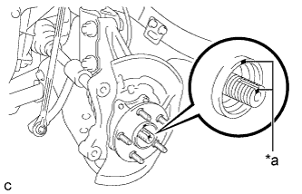 |
Put matchmarks on the front drive shaft assembly and front axle hub sub-assembly.
| *a | Matchmark |
Using a plastic hammer, separate the front drive shaft assembly from the front axle assembly. If it is difficult to separate, tap the end of the front drive shaft assembly using a brass bar and a hammer.
| 13. REMOVE FRONT DRIVE SHAFT ASSEMBLY |
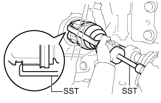 |
Using SST, remove the front drive shaft assembly.
| 14. REMOVE FRONT DRIVE SHAFT HOLE SNAP RING |
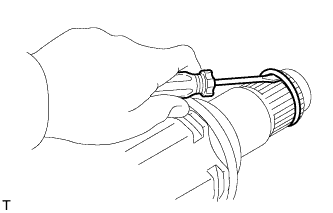 |
Using a screwdriver, remove the front drive shaft hole snap ring.
