FRONT DRIVE SHAFT ASSEMBLY > REASSEMBLY |
| 1. INSTALL FRONT DRIVE SHAFT DUST COVER (for LH Side) |
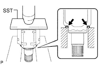 |
Using SST and a press, install a new front drive shaft dust cover into the front drive inboard joint assembly until it is flush with the end.
| 2. INSTALL FRONT DRIVE SHAFT DUST COVER (for RH Side) |
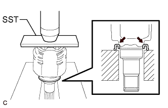 |
Using SST and a press, install a new front drive shaft dust cover into the front drive inboard joint assembly until it is flush with the end.
| 3. INSTALL OUTBOARD JOINT BOOT (for LH Side) |
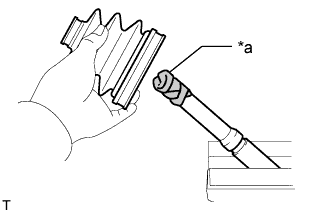 |
Wrap the splines of the front axle outboard joint shaft assembly with protective tape to prevent the boot from being damaged.
| *a | Protective Tape |
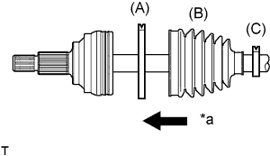 |
Install new parts onto the front axle outboard joint shaft assembly in the following order:
| *a | Outboard Joint Side |
Front No. 2 axle outboard joint boot clamp (A)
Outboard joint boot (B)
Front axle outboard joint boot clamp (C)
Pack the joint portion of the front axle outboard joint shaft assembly and outboard joint boot with grease.
Install the outboard joint boot onto the front axle outboard joint shaft assembly groove.
| 4. INSTALL FRONT NO. 2 AXLE OUTBOARD JOINT BOOT CLAMP (for LH Side) |
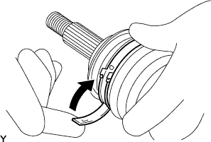 |
Install the front No. 2 axle outboard joint boot clamp onto the outboard joint boot and temporarily fold back the lever.
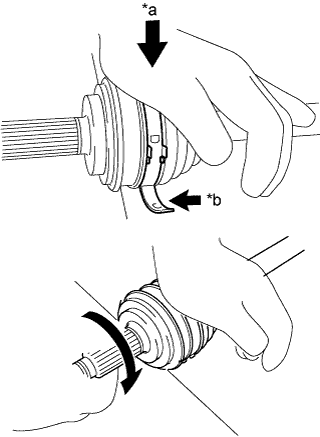 |
Lean your weight on your hand and roll the outboard joint forward while pressing the outboard joint against the work plane. Roll the outboard joint and fold the lever until a click sound can be heard.
| *a | Weight |
| *b | Contact |
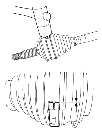 |
Using a plastic hammer, tap the buckle to secure it while adjusting the clearance between the lever and the groove to make the clearance between the buckle edge and the lever end even.
| 5. INSTALL FRONT AXLE OUTBOARD JOINT BOOT CLAMP (for LH Side) |
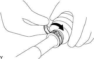 |
Install the front axle outboard joint boot clamp onto the outboard joint boot and temporarily fold back the lever.
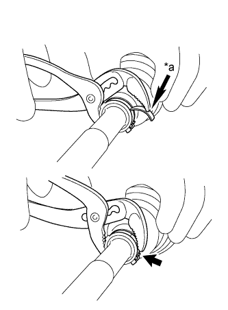 |
Using water pump pliers, pinch the front axle outboard joint boot clamp to temporarily secure it.
| *a | Place the tip near the center of the lever. |
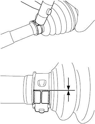 |
Using a plastic hammer, tap the buckle to secure it while adjusting the clearance between the lever and the groove to make the clearance between the buckle edge and the lever end even.
| 6. INSTALL FRONT DRIVE SHAFT DAMPER (for LH Side) |
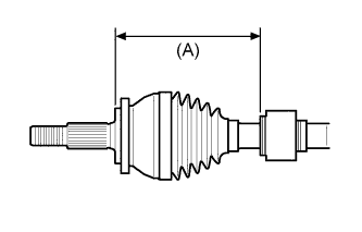 |
Install the front drive shaft damper onto the front axle outboard joint shaft assembly as shown in the illustration.
| 7. INSTALL FRONT DRIVE SHAFT DAMPER (for RH Side) |
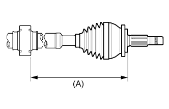 |
Install the front drive shaft damper onto the front axle outboard joint shaft assembly as shown in the illustration.
| 8. INSTALL FRONT DRIVE SHAFT DAMPER CLAMP (for LH Side) |
Secure the front axle outboard joint shaft assembly in a vise using aluminum plates.
for one touch type:
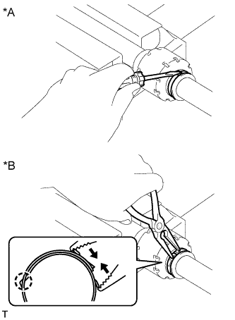 |
Using a screwdriver, install a new front drive shaft damper clamp, as shown in the illustration.
| *A | for One Touch Type |
| *B | for Claw Engagement Type |
for claw engagement type:
Using needle-nose pliers, install a new front drive shaft damper clamp, as shown in the illustration.
| 9. INSTALL FRONT DRIVE SHAFT DAMPER CLAMP (for RH Side) |
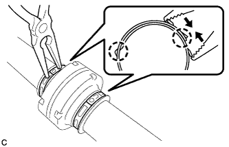 |
Using needle-nose pliers, install 2 new front drive shaft damper clamps, as shown in the illustration.
| 10. INSTALL FRONT DRIVE INBOARD JOINT ASSEMBLY |
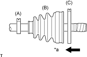 |
Install new parts onto the front axle outboard joint shaft assembly in the following order:
| *a | Outboard Joint Side |
Front axle inboard joint boot clamp (A)
Inboard joint boot (B)
Front No. 2 axle inboard joint boot clamp (C)
Secure the front axle outboard joint shaft assembly in a vise using aluminum plates.
Remove the protective tape.
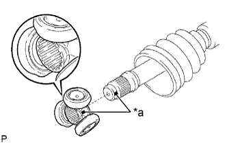 |
Align the matchmarks and install the tripod joint onto the front axle outboard joint shaft assembly as shown in the illustration.
| *a | Matchmark |
Using a brass bar and a hammer, install the tripod joint to the front axle outboard joint shaft assembly.
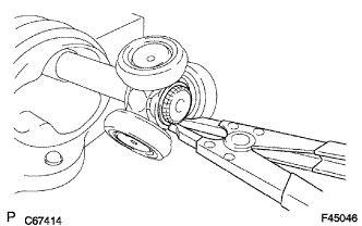 |
Using a snap ring expander, install a new shaft snap ring to the front axle outboard joint shaft assembly.
Pack the front drive inboard joint assembly and inboard joint boot with grease.
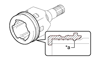 |
Install a new front axle inboard joint grommet onto the inboard joint groove.
| *a | Groove |
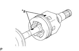 |
Align the matchmarks and install the front drive inboard joint assembly onto the front axle outboard joint shaft assembly.
| *a | Matchmark |
| 11. INSTALL INBOARD JOINT BOOT |
Install the inboard joint boot into the grooves of the inboard joint grommet and inboard joint boot.
| 12. INSTALL FRONT NO. 2 AXLE INBOARD JOINT BOOT CLAMP |
Install the boot clamp onto the inboard joint boot.
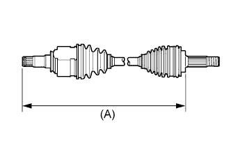 |
Adjust dimension (A) until it is within the specified length.
| LH Side | RH Side |
| 552.2 to 560.2 mm (1.81 to 1.84 ft.) | 901.2 to 909.2 mm (2.96 to 2.98 ft.) |
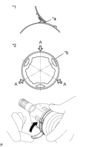 |
While keeping dimension (A) within the specified length, put the inside of the inboard joint under atmospheric pressure by pulling the recessed parts on the inboard joint grommet out.
| *1 | Boot Clamp |
| *2 | Inboard Joint Grommet |
| *a | Fulcrum Point |
| *b | Recessed Parts |
Set the lever fulcrum point at any point A indicated in the illustration and temporarily bend the lever.
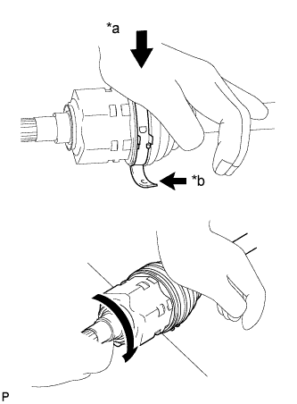 |
Lean your weight on your hand and roll the inboard joint forward while pressing the inboard joint against the work plane. Roll the inboard joint and fold the lever until a click sound can be heard.
| *a | Weight |
| *b | Contact |
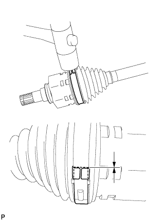 |
Using a plastic hammer, tap the buckle to secure it while adjusting the clearance between the lever and the groove to make the clearance between the buckle edge and the lever end even.
| 13. INSTALL FRONT AXLE INBOARD JOINT BOOT CLAMP |
|
Install the front axle inboard joint boot clamp onto the inboard joint boot and temporarily fold back the lever.
|
Using water pump pliers, pinch the front axle outboard joint boot clamp to temporarily secure it.
| *a | Place the tip near the center of the lever. |
|
Using a plastic hammer, tap the buckle to secure it while adjusting the clearance between the lever and the groove to make the clearance between the buckle edge and the lever end even.
| 14. INSPECT FRONT DRIVE SHAFT ASSEMBLY |
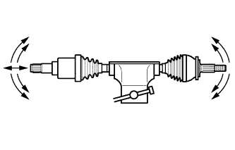 |
Check that there is no excessive play in the outboard joint.
Check that the inboard joint slides smoothly in the thrust direction.
Check that there is no excessive play in the radial directions of the inboard joint.
|
Check the boots for damage.
| LH Side | RH Side |
| 552.2 to 560.2 mm (1.81 to 1.84 ft.) | 901.2 to 909.2 mm (2.96 to 2.98 ft.) |
