AIR CONDITIONING UNIT > INSTALLATION |
| 1. TEMPORARILY TIGHTEN AIR CONDITIONING UNIT ASSEMBLY |
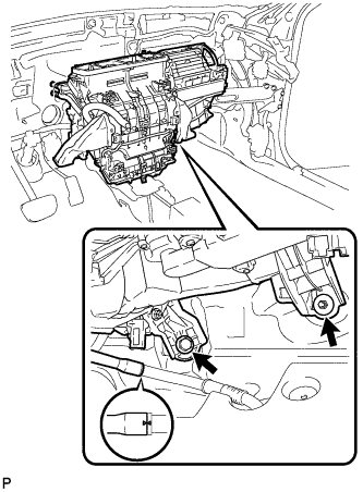 |
Temporarily tighten the air conditioning unit assembly with the bolt and nut.
Engage the cooler drain hose as shown in the illustration.
| 2. INSTALL INSTRUMENT PANEL REINFORCEMENT |
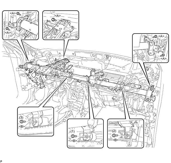
Install the instrument panel reinforcement assembly with the 5 bolts <A>.
Install the air conditioning unit assembly with the 3 bolts <B>.
Connect the center airbag sensor connectors to the center airbag sensor assembly as shown in the illustration.
Check that the waterproof sheet on the top of the center airbag sensor is not folded or deformed.
Check that there is no looseness in the installation parts of the center airbag sensor assembly.
Engage each clamp.
Connect each connector.
Install the 2 bolts and connect the 2 earth wires.
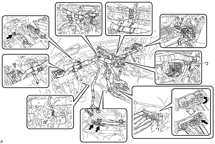
| *1 | Center airbag sensor connector | *2 | Earth wire |
w/ PTC Heater:
Connect the 2 connectors.
Install the brake pedal support assembly to the instrument panel reinforcement with the bolt.
| 3. INSTALL ECU INTEGRATION BOX RH (for LHD) |
Install the ECU integration box RH with the 2 nuts and bolt.
Engage the clamp to connect the wire harness.
Connect each connector.
| 4. INSTALL ECU INTEGRATION BOX RH (for RHD) |
Install the ECU integration box RH with the nut.
Install the bolt.
Engage the clamp.
Connect each connector.
| 5. INSTALL ECU INTEGRATION BOX LH (for RHD) |
Install the ECU integration box LH with the nut and bolt.
Engage the clamp to connect the wire harness.
Connect each connector.
| 6. INSTALL INSTRUMENT PANEL JUNCTION BLOCK ASSEMBLY (for LHD) |
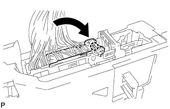 |
Engage the claw to install the connector as shown in the illustration.
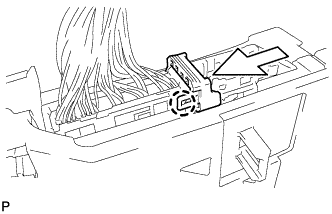 |
Engage the claw to lock the connector lock as shown in the illustration.
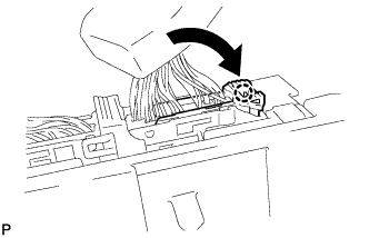 |
Engage the claw to connect the connector as shown in the illustration.
Engage the 2 clamps to connect the wire harness.
Install the instrument panel junction block assembly with the bolt and nut.
Connect each connector.
| 7. INSTALL INSTRUMENT PANEL JUNCTION BLOCK ASSEMBLY (for RHD) |
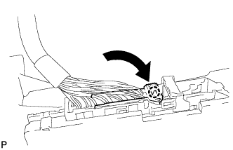 |
Engage the claw to install the connector as shown in the illustration.
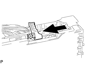 |
Engage the claw to lock the connector lock as shown in the illustration.
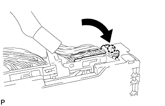 |
Engage the claw to connect the connector as shown in the illustration.
Install the instrument panel junction block assembly with the bolt and nut.
Connect each connector.
| 8. INSTALL CENTER INSTRUMENT PANEL TO COWL BRACE |
Engage the guide.
Install the center instrument panel to cowl brace with the 2 bolts.
| 9. INSTALL LOWER DEFROSTER NOZZLE ASSEMBLY |
Engage the 6 claws.
Install the lower defroster nozzle assembly with the 2 clips.
| 10. INSTALL NO. 2 HEATER TO REGISTER DUCT |
Install the No. 2 heater to register duct with the 3 clips.
| 11. INSTALL REAR NO. 1 AIR DUCT |
Engage the 2 claws and install the rear No. 1 air duct.
| 12. INSTALL REAR NO. 2 AIR DUCT |
Engage the 2 claws and install the rear No. 2 air duct.
| 13. INSTALL NO. 2 INSTRUMENT PANEL BRACE SUB-ASSEMBLY |
Install the screw.
Install the No. 2 instrument panel brace sub-assembly with the bolt and nut.
Engage each clamp.
Install the bolt and connect the earth wire.
| 14. INSTALL NO. 1 INSTRUMENT PANEL BRACE SUB-ASSEMBLY |
Install the screw.
Install the No. 1 instrument panel brace sub-assembly with the bolt and nut.
Engage each clamp.
Install the bolt and connect the earth wire.
| 15. INSTALL CENTER INSTRUMENT PANEL REINFORCEMENT SUB-ASSEMBLY |
Install the center instrument panel reinforcement sub-assembly with the bolt and nut.
| 16. INSTALL WINDSHIELD WIPER RELAY ASSEMBLY |
Install the windshield wiper relay assembly with the bolt.
Connect the connector.
| 17. INSTALL AIR CONDITIONING UNIT ASSEMBLY |
Install the air conditioning unit assembly with the bolt and nut.
| 18. CONNECT NO. 2 STEERING INTERMEDIATE SHAFT ASSEMBLY |
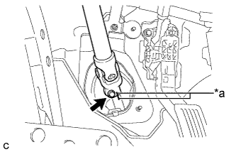 |
Align the matchmarks on the No. 2 steering intermediate shaft assembly and steering intermediate shaft to connect the No. 2 steering intermediate shaft assembly to the steering intermediate shaft.
| *a | Matchmark |
Install the bolt.
| 19. INSTALL STEERING POST ASSEMBLY (for LHD) |
Install the steering post assembly with the bolt and 2 nuts.
Engage the wire harness clamps to the steering post assembly.
Engage the 2 wire harness clamps.
Connect the connector to the power steering ECU assembly.
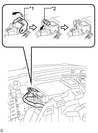 |
Connect the connector to the power steering ECU assembly.
| *1 | Lock Lever |
| *2 | Lock of Lock Lever |
| 20. INSTALL STEERING POST ASSEMBLY (for RHD) |
Install the steering post assembly with the bolt and 2 nuts.
Engage the wire harness clamps to the steering post assembly.
Engage the 2 wire harness clamps.
| 21. INSTALL COLUMN HOLE COVER SILENCER SHEET |
Install the column hole cover silencer sheet with the 2 clips.
Install the floor carpet.
| 22. INSTALL NO. 1 AIR DUCT SUB-ASSEMBLY (for LHD) |
Engage the 2 claws to install the rear No. 1 air duct sub-assembly.
| 23. INSTALL NO. 2 AIR DUCT SUB-ASSEMBLY (for RHD) |
Engage the 2 claws to install the rear No. 2 air duct sub-assembly.
| 24. INSTALL TURN SIGNAL SWITCH ASSEMBLY WITH SPIRAL CABLE SUB-ASSEMBLY |
Using pliers, expand the clamp.
While holding the clamp expanded, install the turn signal switch assembly with spiral cable sub-assembly to the steering post assembly and engage the claw.
Return the clamp to its original position.
Connect the connectors to the turn signal switch assembly with spiral cable sub-assembly.
| 25. INSTALL STEERING COLUMN COVER |
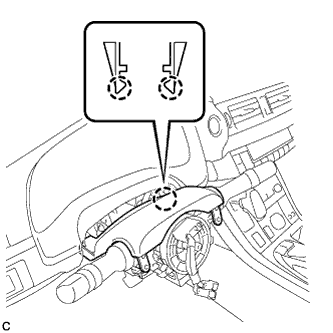 |
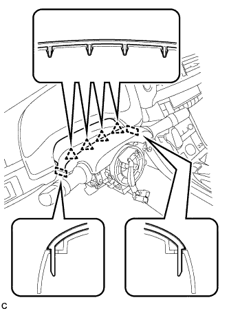
Engage the 2 claws to install the steering column cover (upper side).
 |
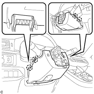
Engage the 4 clips and 2 guides to the steering column cover (upper side).
 |
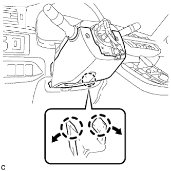
Engage the 4 claws to install the steering column cover (lower side).
 |
Engage the 2 claws.
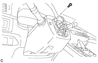 |
Install the 2 screws.
| 26. INSTALL BRAKE PEDAL SUPPORT ASSEMBLY (for RHD) |
Install the nut to the brake pedal support assembly.
Install the brake pedal support assembly with the 4 nuts.
Engage the clamp.
Install the brake pedal support assembly to the instrument panel reinforcement with the bolt.
| 27. INSTALL PUSH ROD PIN (for RHD) |
Apply lithium soap base glycol grease to the push rod pin and installation hole of the brake pedal support assembly.
Install the push rod pin and a new clip to connect the push rod clevis to the brake pedal support assembly.
| 28. INSTALL BRAKE PEDAL RETURN SPRING (for RHD) |
Install the brake pedal return spring to the brake pedal support assembly and push rod pin.
| 29. INSTALL STOP LIGHT SWITCH MOUNTING ADJUSTER |
| 30. INSTALL STOP LIGHT SWITCH ASSEMBLY |
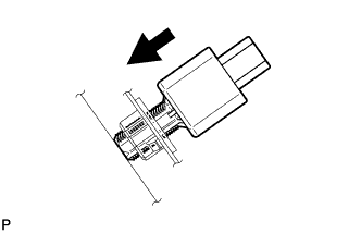 |
Insert the stop light switch assembly until the rod hits the pedal.
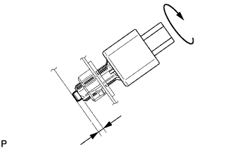 |
Make a quarter turn clockwise to install the stop light switch assembly.
Connect the connector.
Check the protrusion of the rod.
| 31. INSTALL POWER STEERING ECU ASSEMBLY (for LHD) |
Install the power steering ECU assembly with the bolt and 2 nuts.
Connect the 3 connectors to the power steering ECU assembly.
|
Connect the connector to the power steering ECU assembly.
| *1 | Lock Lever |
| *2 | Lock of the Lock Lever |
| 32. INSTALL POWER STEERING ECU ASSEMBLY (for RHD) |
Install the power steering ECU assembly with the bolt and 2 nuts.
Connect the 3 connectors to the power steering ECU assembly.
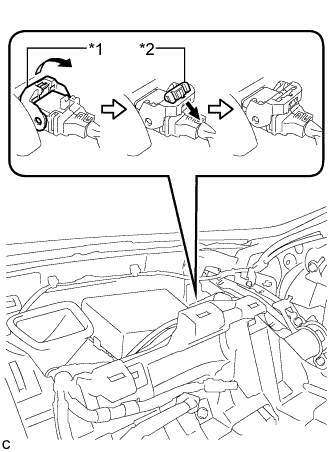 |
Connect the connector to the power steering ECU assembly.
| *1 | Lock Lever |
| *2 | Lock of the Lock Lever |
| 33. INSTALL LOWER INSTRUMENT PANEL SUB-ASSEMBLY |
| 34. CONNECT OUTLET HEATER WATER HOSE |
Using pliers, grip the claws of the clip and slide the clip to connect the outlet heater water hose.
| 35. CONNECT INLET HEATER WATER HOSE |
Using pliers, grip the claws of the clip and slide the clip to connect the inlet heater water hose.
| 36. CONNECT AIR CONDITIONING TUBE AND ACCESSORY ASSEMBLY |
Remove the attached vinyl tape from the pipe.
Apply a sufficiently amount of compressor oil to a new O-ring and the fitting surface of the air conditioning tube and accessory assembly.
Install the O-ring on the air conditioning tube and accessory assembly.
Install the air conditioning tube and accessory assembly.
| 37. CONNECT SUCTION PIPE SUB-ASSEMBLY |
Remove the attached vinyl tape from the pipe.
Apply a sufficient amount of compressor oil to a new O-ring and the fitting surface of the suction pipe sub-assembly.
Install the O-ring on the suction pipe sub-assembly.
Install the suction pipe sub-assembly.
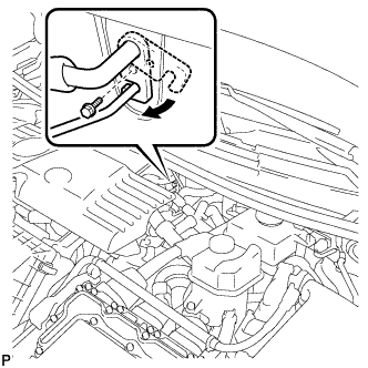 |
Move the hook connector in the direction indicated by the arrow in the illustration.
Insert the pipe joint into the fitting hole securely and tighten the bolt.
| 38. INSTALL RESERVOIR TUBE ASSEMBLY (for RHD) |
Install the reservoir tube assembly with the 2 bolts and nut.
| 39. INSTALL OUTER COWL TOP PANEL SUB-ASSEMBLY (for RHD) |
Install the outer cowl top panel sub-assembly with the 9 bolts.
w/ Wiper Deicer:
Engage the 3 clamps to install the wire harness.
Engage the clamp to install the wire harness.
| 40. INSTALL COWL BODY MOUNTING REINFORCEMENT RH (for RHD) |
Install the cowl body mounting reinforcement RH with the 2 bolts.
| 41. INSTALL NO. 2 HEATER AIR DUCT SPLASH SHIELD SEAL (for RHD) |
Engage the claw and guide to install the No. 2 heater air duct splash shield seal.
| 42. INSTALL NO. 1 HEATER AIR DUCT SPLASH SHIELD SEAL (for RHD) |
Engage the 2 claws to install the No. 1 heater air duct splash shield seal.
| 43. INSTALL WINDSHIELD WIPER MOTOR AND LINK ASSEMBLY (for RHD) |
| 44. ALIGN FRONT WHEELS FACING STRAIGHT AHEAD |
| 45. ADJUST SPIRAL WITH SENSOR CABLE SUB-ASSEMBLY |
Check that the power switch is off.
Check that the cable is disconnected from the negative (-) auxiliary battery terminal.
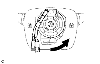 |
Rotate the spiral cable counterclockwise slowly by hand until it stops.
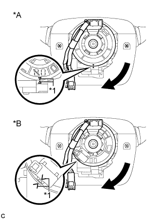 |
Rotate the spiral cable clockwise approximately 2.5 turns to align the marks.
| *A | w/o Steering Heater |
| *B | w/ Steering Heater |
| *1 | Alignment Mark |
| 46. INSTALL STEERING WHEEL ASSEMBLY |
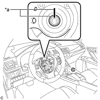 |
Install the steering wheel assembly aligning the matchmarks on the steering wheel assembly and steering main shaft.
| *a | Matchmark |
Install the steering wheel assembly set nut.
Connect the connectors to the spiral cable and steering wheel assembly.
| 47. CHECK STEERING WHEEL CENTER POINT |
| 48. INSTALL HORN BUTTON ASSEMBLY |
| 49. INSPECT AND ADJUST BRAKE PEDAL |
| 50. ADD ENGINE COOLANT (for Engine) |
Tighten the radiator drain cock plug.
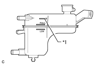 |
Add coolant to B line of the reserve tank.
| *1 | B Line |
| Item | Capacity |
| Engine coolant | w/ Exhaust Heat Recirculation System: 6.9 liters (7.3 US qts, 6.1 lmp. qts) |
| w/o Exhaust Heat Recirculation System: 6.5 liters (6.9 US qts, 5.7 lmp. qts) |
Squeeze the radiator hoses several times by hand, and then check the level of the coolant.
If the coolant level is low, add coolant.
Put the engine in inspection mode (Click here).
Install the reserve tank cap.
Bleed air from the cooling system.
Warm up the engine until the thermostat opens. While the thermostat is open, allow the coolant to circulate for several minutes. (●1)
Stop the engine and wait until the coolant cools down. Then if the coolant level is below the low line, add coolant so that the level will be between the full and low lines. (●2)
Repeat the steps from (●1) to (●2) until the coolant level of the reserve tank remains above the low line.
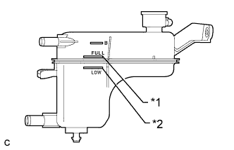 |
After the engine has cooled down, check that the coolant level is between the full and low lines.
| *1 | Full Line |
| *2 | Low Line |
| 51. CHARGE AIR CONDITIONING SYSTEM WITH REFRIGERANT |
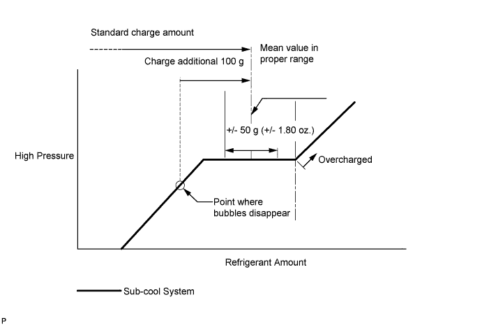
Perform vacuum purging using a vacuum pump or appropriate equipment.
Charge the air conditioning system with refrigerant.
| 52. WARM UP COMPRESSOR |
Keep the A/C switch on for at least 2 minutes to warm up the compressor.
| 53. INSPECT FOR REFRIGERANT LEAK |
After recharging the air conditioning system with refrigerant, inspect for refrigerant leaks using a halogen leak detector.
Carry out the test under the following conditions:
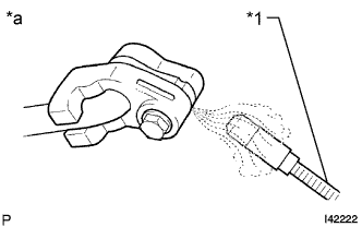 |
Using a halogen leak detector, inspect for refrigerant leaks from the air conditioning system.
| *1 | Halogen Leak Detector |
| *a | Inspect for Leak |
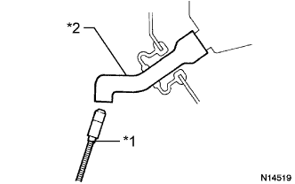 |
Bring the halogen leak detector close to the drain hose with the detector power off, and then turn the detector on.
| *1 | Halogen Leak Detector |
| *2 | Drain Hose |
If a refrigerant leak is not detected from the drain hose, remove the blower motor control from the cooling unit. Insert the halogen leak detector sensor into the unit and check for a leak.
Disconnect the pressure sensor connector and leave it for approximately 20 minutes. Bring the halogen leak detector close to the pressure sensor and check for a leak.
| 54. INSPECT FOR COOLANT LEAK (for Engine) |
Remove the reserve tank cap.
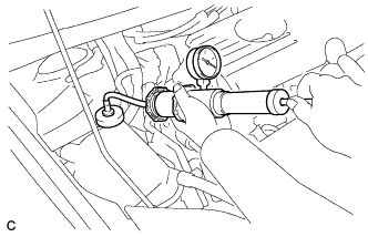 |
Fill the reserve tank with coolant, and then attach a radiator cap tester.
Put the engine in inspection mode (Click here).
Warm up the engine.
Using a radiator cap tester, increase the pressure inside the radiator to 108 kPa (1.1 kgf/cm2, 16 psi), and check that the pressure does not drop. If the pressure drops, check the hoses, radiator, front exhaust pipe assembly, the heater hose around the engine coolant temperature sensor and engine water pump assembly for leaks. If no external leaks are found, check the heater core, cylinder block and cylinder head.
Remove the radiator cap tester.
Install the reserve tank cap.
| 55. INITIALIZATION SERVO MOTOR |
