AIR CONDITIONING UNIT > REMOVAL |
| 1. RECOVER REFRIGERANT FROM AIR CONDITIONING SYSTEM |
Turn the A/C switch on.
Operate the air conditioning with a set temperature of 25°C (77°F) and the blower at low for 10 minutes to circulate the refrigerant. This causes most of the compressor oil from the various components of the air conditioning system to collect in the air conditioning compressor.
Turn the power switch off.
Recover the refrigerant from the air conditioning system using a refrigerant recovery unit.
| 2. REMOVE WINDSHIELD WIPER MOTOR AND LINK ASSEMBLY (for RHD) |
| 3. REMOVE NO. 1 HEATER AIR DUCT SPLASH SHIELD SEAL (for RHD) |
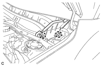 |
Disengage the 2 claws and remove the No. 1 heater air duct splash shield seal.
| 4. REMOVE NO. 2 HEATER AIR DUCT SPLASH SHIELD SEAL (for RHD) |
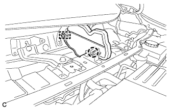 |
Disengage the claw and guide, and remove the No. 2 heater air duct splash shield seal.
| 5. REMOVE COWL BODY MOUNTING REINFORCEMENT RH (for RHD) |
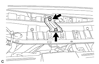 |
Remove the 2 bolts and cowl body mounting reinforcement RH.
| 6. REMOVE OUTER COWL TOP PANEL SUB-ASSEMBLY (for RHD) |
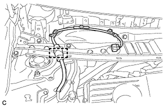 |
Disengage the clamp and separate the wire harness.
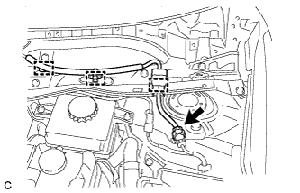 |
w/ Wiper Deicer:
Disengage the 3 clamps, disconnect the connector and separate the wire harness.
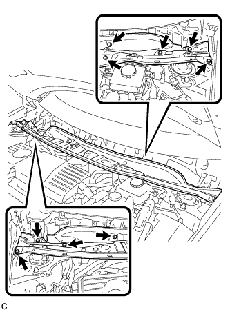 |
Remove the 9 bolts and outer cowl top panel sub-assembly.
| 7. SEPARATE RESERVOIR TUBE ASSEMBLY (for RHD) |
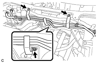 |
Remove the 2 bolts, nut and separate the reservoir tube assembly.
| 8. DISCONNECT SUCTION PIPE SUB-ASSEMBLY |
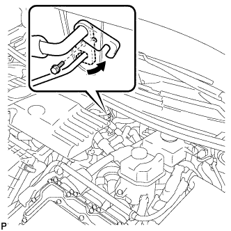 |
Remove the bolt and slide the hook connector.
Disconnect the suction pipe sub-assembly.
Remove the O-ring from the suction pipe sub-assembly.
| 9. DISCONNECT AIR CONDITIONING TUBE AND ACCESSORY ASSEMBLY |
Disconnect the air conditioning tube and accessory assembly.
Remove the O-ring from the air conditioning tube and accessory assembly.
| 10. DISCONNECT OUTLET HEATER WATER HOSE |
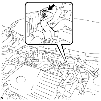 |
Using pliers, grip the claws of the clip and slide the clip to disconnect the outlet heater water hose.
| 11. DISCONNECT INLET HEATER WATER HOSE |
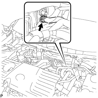 |
Using pliers, grip the claws of the clip and slide the clip to disconnect the inlet heater water hose.
| 12. REMOVE LOWER INSTRUMENT PANEL SUB-ASSEMBLY |
| 13. REMOVE STOP LIGHT SWITCH ASSEMBLY |
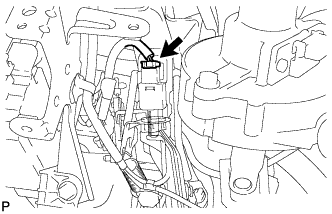 |
Disconnect the connector.
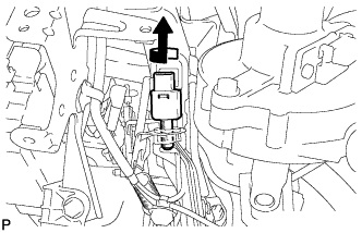 |
Turn the stop light switch assembly counterclockwise and remove it.
| 14. REMOVE STOP LIGHT SWITCH MOUNTING ADJUSTER |
| 15. REMOVE BRAKE PEDAL RETURN SPRING (for RHD) |
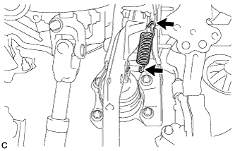 |
Remove the brake pedal return spring from the brake pedal support assembly and push rod pin.
| 16. REMOVE PUSH ROD PIN (for RHD) |
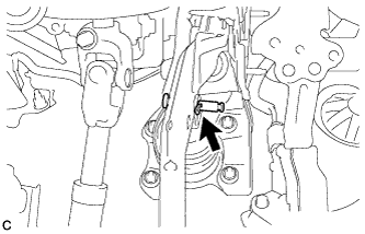 |
Remove the clip and push rod pin to separate the brake pedal support assembly from the push rod clevis.
| 17. REMOVE BRAKE PEDAL SUPPORT ASSEMBLY (for RHD) |
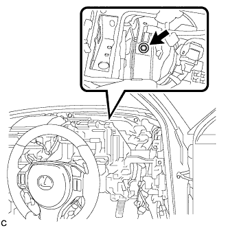 |
Remove the bolt and separate the brake pedal support assembly from the instrument panel reinforcement.
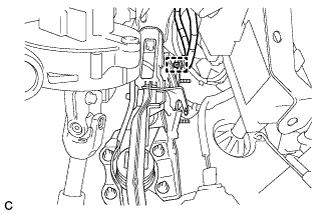 |
Disengage the clamp.
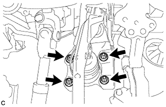 |
Remove the 4 nuts and brake pedal support assembly.
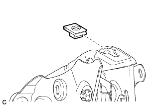 |
Remove the nut from the brake pedal support assembly.
| 18. REMOVE POWER STEERING ECU ASSEMBLY (for LHD) |
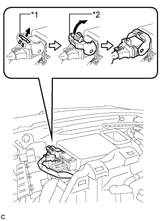 |
Disconnect the connector from the power steering ECU assembly.
| *1 | Lock of the Lock Lever |
| *2 | Lock Lever |
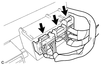 |
Disconnect the 3 connectors from the power steering ECU assembly.
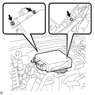 |
Remove the bolt, 2 nuts and power steering ECU assembly.
| 19. REMOVE POWER STEERING ECU ASSEMBLY (for RHD) |
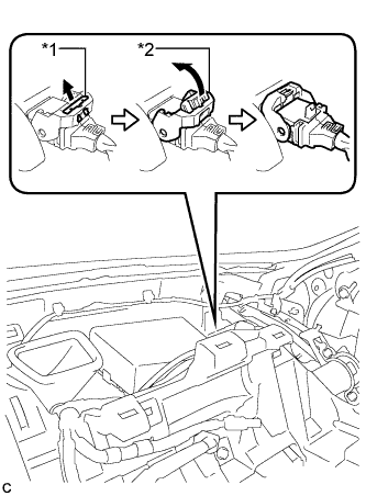 |
Disconnect the connector from the power steering ECU assembly.
| *1 | Lock of the Lock Lever |
| *2 | Lock Lever |
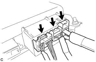 |
Disconnect the 3 connectors from the power steering ECU assembly.
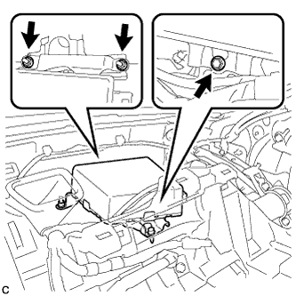 |
Remove the bolt, 2 nuts and power steering ECU assembly.
| 20. ALIGN FRONT WHEELS FACING STRAIGHT AHEAD |
| 21. REMOVE HORN BUTTON ASSEMBLY |
| 22. REMOVE STEERING WHEEL ASSEMBLY |
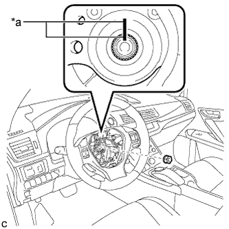 |
Remove the steering wheel assembly set nut.
| *a | Matchmark |
Put matchmarks on the steering wheel assembly and steering main shaft.
Disconnect the connectors from the spiral cable and steering wheel assembly.
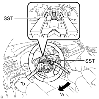 |
Using SST, remove the steering wheel assembly.
| *a | Turn |
| *b | Hold |
| 23. REMOVE STEERING COLUMN COVER |
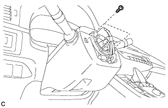 |
Remove the 2 screws.
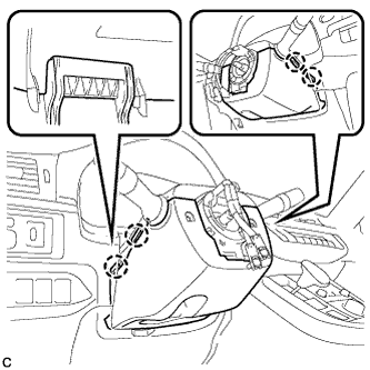 |
Push the right and left sides of the steering column cover (lower side) to disengage the 4 claws.
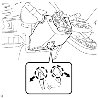 |
Insert fingers into the opening of the tilt lever of the steering column cover (lower side) to disengage the 2 claws and remove the steering column cover (lower side).
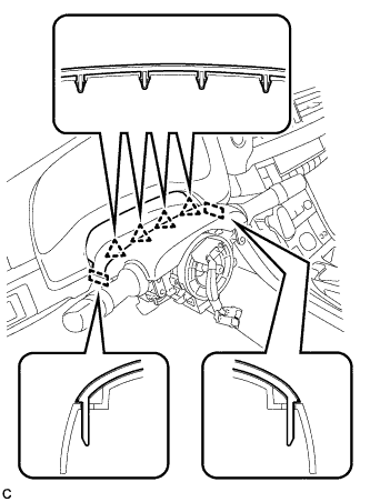 |
Disengage the 4 clips and 2 guides from the steering column cover (upper side).
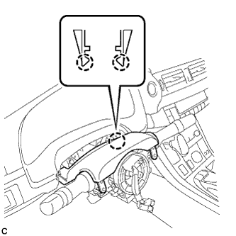 |
Disengage the 2 claws to remove the steering column cover (upper side).
| 24. REMOVE TURN SIGNAL SWITCH ASSEMBLY WITH SPIRAL CABLE SUB-ASSEMBLY |
Disconnect the connectors from the turn signal switch assembly with spiral cable sub-assembly.
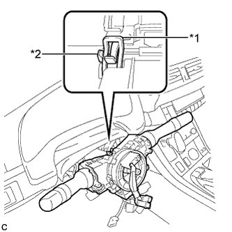 |
Using pliers, expand the clamp.
| *1 | Clamp |
| *2 | Claw |
While holding the clamp expanded, raise the claw using a screwdriver to disengage it, and then remove the turn signal switch assembly with spiral cable sub-assembly from the steering post assembly.
| 25. REMOVE NO. 1 AIR DUCT SUB-ASSEMBLY (for LHD) |
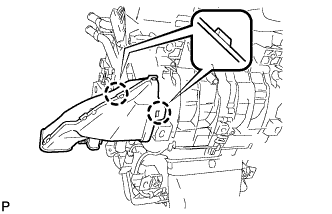 |
Disengage the 2 claws and remove the rear No. 1 air duct sub-assembly.
| 26. REMOVE NO. 2 AIR DUCT SUB-ASSEMBLY (for RHD) |
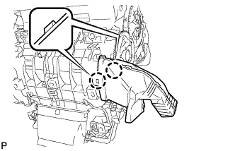 |
Disengage the 2 claws and remove the rear No. 2 air duct sub-assembly.
| 27. REMOVE COLUMN HOLE COVER SILENCER SHEET |
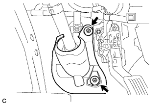 |
Turn back the floor carpet.
Remove the 2 clips and column hole cover silencer sheet.
| 28. REMOVE STEERING POST ASSEMBLY (for LHD) |
|
Disconnect the connector from the power steering ECU assembly.
| *1 | Lock of Lock Lever |
| *2 | Lock Lever |
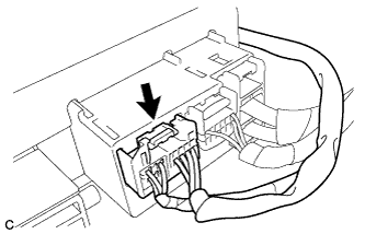 |
Disconnect the connector from the power steering ECU assembly.
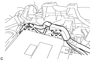 |
Disengage the 2 wire harness clamps.
Disengage the wire harness clamps from the steering post assembly.
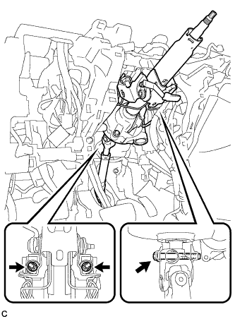 |
Remove the bolt, 2 nuts and steering post assembly.
| 29. REMOVE STEERING POST ASSEMBLY (for RHD) |
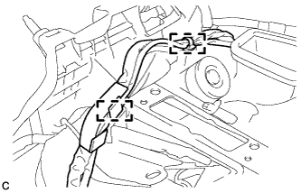 |
Disengage the 2 wire harness clamps.
Disengage the wire harness clamps from the steering post assembly.
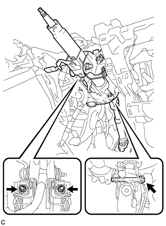 |
Remove the bolt, 2 nuts and steering post assembly.
| 30. SEPARATE NO. 2 STEERING INTERMEDIATE SHAFT ASSEMBLY |
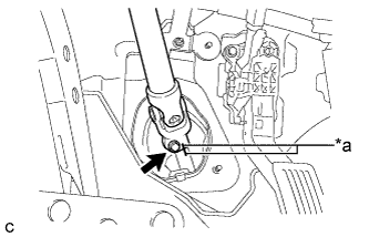 |
Put matchmarks on the No. 2 steering intermediate shaft assembly and steering intermediate shaft.
| *a | Matchmark |
Remove the bolt.
Separate the No. 2 steering intermediate shaft assembly from the steering intermediate shaft.
| 31. REMOVE WINDSHIELD WIPER RELAY ASSEMBLY |
 |
Disconnect the connector.
Remove the bolt and windshield wiper relay assembly.
| 32. REMOVE CENTER INSTRUMENT PANEL REINFORCEMENT SUB-ASSEMBLY |
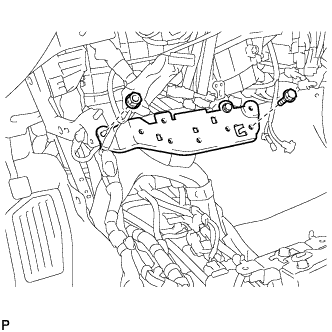 |
Remove the bolt, nut and center instrument panel reinforcement sub-assembly.
| 33. REMOVE NO. 1 INSTRUMENT PANEL BRACE SUB-ASSEMBLY |
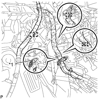 |
Disconnect each connector.
| *1 | Earth Wire |
Disengage each clamp.
Remove the bolt and disconnect the earth wire.
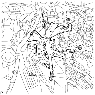 |
Remove the screw.
Remove the bolt, nut and No. 1 instrument panel brace sub-assembly.
| 34. REMOVE NO. 2 INSTRUMENT PANEL BRACE SUB-ASSEMBLY |
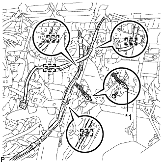 |
Disengage each clamp.
| *1 | Earth Wire |
Remove the bolt and disconnect the earth wire.
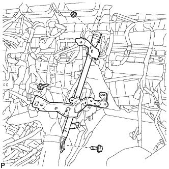 |
Remove the screw.
Remove the bolt, nut and No. 2 instrument panel brace sub-assembly.
| 35. REMOVE REAR NO. 2 AIR DUCT |
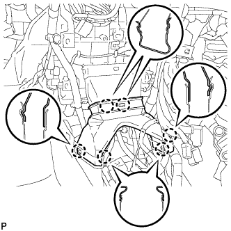 |
Disengage the 6 claws and remove the rear No. 2 air duct.
| 36. REMOVE REAR NO. 1 AIR DUCT |
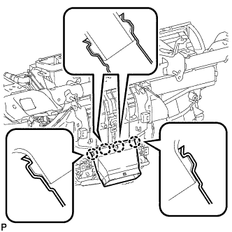 |
Disengage the 4 claws and remove the rear No. 1 air duct.
| 37. REMOVE NO. 2 HEATER TO REGISTER DUCT |
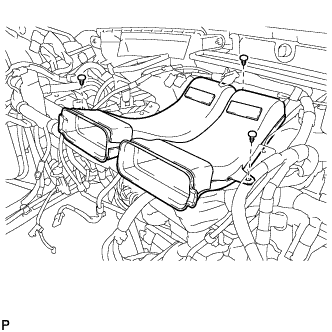 |
Remove the 3 clips and No. 2 heater to register duct.
| 38. REMOVE LOWER DEFROSTER NOZZLE ASSEMBLY |
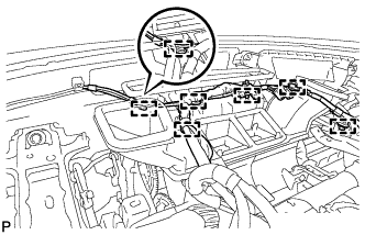 |
Disengage each clamp.
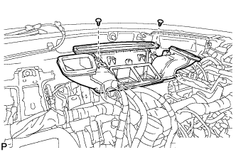 |
Remove the 2 clips.
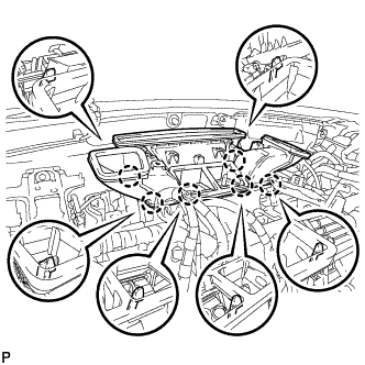 |
Disengage the 6 claws and remove the lower defroster nozzle assembly.
| 39. REMOVE CENTER INSTRUMENT PANEL TO COWL BRACE |
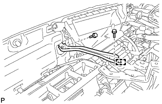 |
Remove the 2 bolts.
Disengage the guide and remove the instrument panel reinforcement.
| 40. REMOVE INSTRUMENT PANEL JUNCTION BLOCK ASSEMBLY (for LHD) |
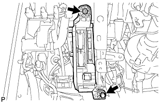 |
Disconnect each connector.
Remove the bolt and nut, and disconnect the instrument panel junction block assembly.
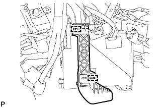 |
Disengage the 2 clamps and disconnect the wire harness.
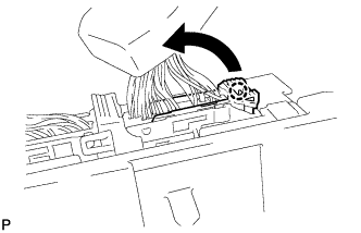 |
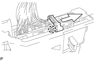
Disengage the claw and disconnect the connector as shown in the illustration.
 |
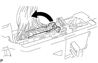
Disengage the claw and release the connector lock as shown in the illustration.
 |
Disengage the claw and disconnect the connector as shown in the illustration.
Remove the instrument panel junction block assembly.
| 41. REMOVE INSTRUMENT PANEL JUNCTION BLOCK ASSEMBLY (for RHD) |
Disconnect each connector.
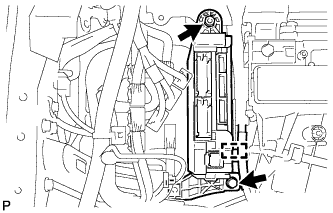 |
Disengage the clamp.
Remove the bolt and nut, and disconnect the instrument panel junction block assembly.
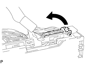 |
Disengage the claw and disconnect the connector as shown in the illustration.
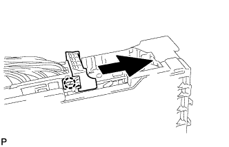 |
Disengage the claw and release the connector lock as shown in the illustration.
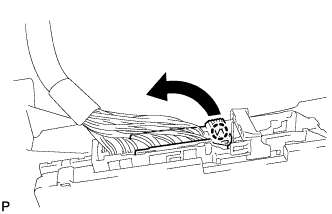 |
Disengage the claw and disconnect the connector as shown in the illustration.
Remove the instrument panel junction block assembly.
| 42. REMOVE ECU INTEGRATION BOX RH (for LHD) |
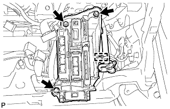 |
Disconnect each connector.
Disengage the clamp and disconnect the wire harness.
Remove the bolt, 2 nuts and ECU integration box RH.
| 43. REMOVE ECU INTEGRATION BOX LH (for RHD) |
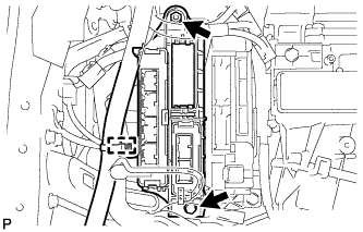 |
Disconnect each connector.
Disengage the clamp and disconnect the wire harness.
Remove the bolt, nut and ECU integration box LH.
| 44. REMOVE ECU INTEGRATION BOX RH (for RHD) |
Disconnect each connector.
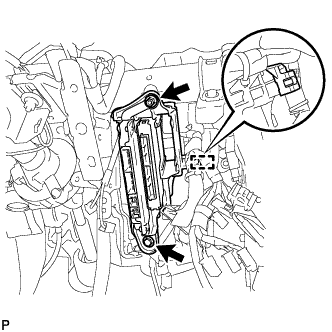 |
Disengage the clamp.
Remove the bolt.
Remove the nut and ECU integration box RH.
| 45. REMOVE INSTRUMENT PANEL REINFORCEMENT |
Disconnect the center airbag sensor connectors from the center airbag sensor assembly as shown in the illustration.
Remove the 2 bolts and disconnect the 2 earth wires.
Remove the 3 bolts.
w/ PTC Heater:
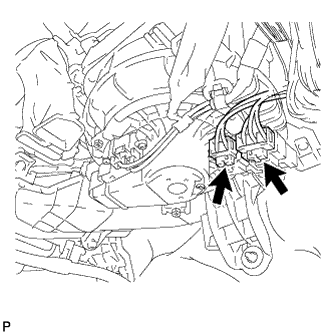 |
Disconnect the 2 connectors.
Disconnect each connector.
Disengage each clamp.
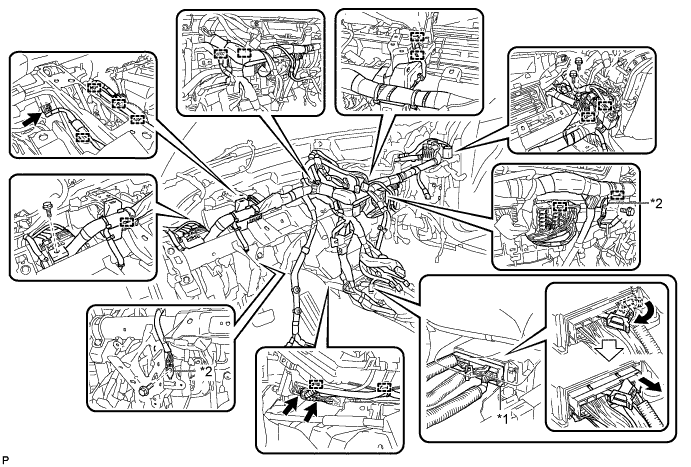
| *1 | Center Airbag Sensor Connector | *2 | Earth wire |
for LHD:
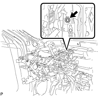 |
Remove the bolt and separate the brake pedal support assembly from the instrument panel reinforcement.
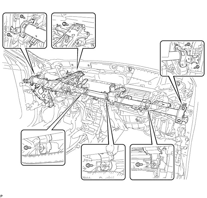
Remove the 8 bolts and instrument panel reinforcement.
| 46. REMOVE AIR CONDITIONING UNIT ASSEMBLY |
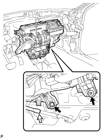 |
Disengage the clamp.
Disengage the cooler drain hose.
Remove the bolt, nut and air conditioning unit assembly.
