AIR CONDITIONING UNIT > REASSEMBLY |
| 1. INSTALL NO. 1 COOLER THERMISTOR |
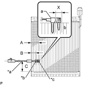 |
Install the No. 1 cooler thermistor as shown in the illustration.
| Part | Length | |
| A | 34.3 mm | 1.35 in. |
| B | 20.9 mm | 0.822 in. |
| C | 50 mm | 1.97 in. |
| *a | From Tank |
| *b | Fixed Part |
| *c | Sensor Part |
| 2. INSTALL COOLER EVAPORATOR SUB-ASSEMBLY |
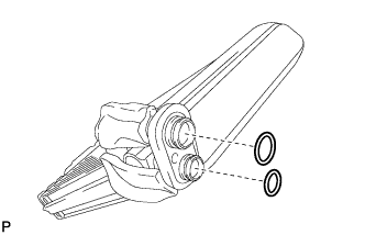 |
Apply a sufficient amount of compressor oil to 2 new O-rings and the fitting surfaces.
Install the 2 O-rings to the cooler evaporator subassembly.
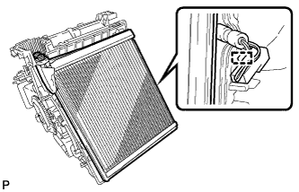 |
Engage the clamp and install the cooler evaporator sub-assembly with the No. 1 cooler thermistor.
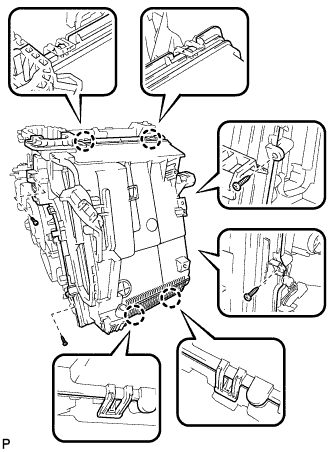 |
Engage the 4 claws.
Install the lower heater case with the 4 screws.
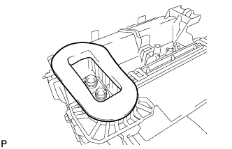 |
Install the packing.
| 3. INSTALL COOLER EXPANSION VALVE |
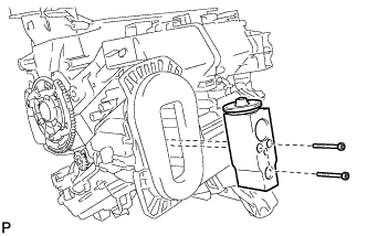 |
Using a 4 mm hexagon wrench, install the cooler expansion valve with the 2 hexagon bolts.
| 4. INSTALL DRAIN COOLER HOSE |
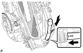 |
Install the drain cooler hose as shown in the illustration.
| 5. INSTALL AIR CONDITIONING AMPLIFIER ASSEMBLY |
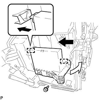 |
Engage the 2 guides to install the air conditioning amplifier assembly as shown in the illustration.
Install the screw.
| 6. INSTALL CONSOLE MOUNTING BRACKET RH |
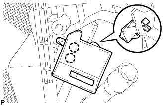 |
Engage the 2 claws and install the console mounting bracket RH.
| 7. INSTALL CONSOLE MOUNTING BRACKET LH |
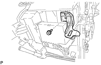 |
Install the console mounting bracket LH with the screw.
| 8. INSTALL HEATER RADIATOR UNIT SUB-ASSEMBLY |
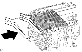 |
Install the heater radiator unit sub-assembly as shown in the illustration.
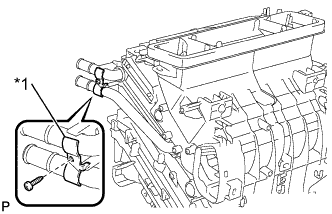 |
Install the clamp with the screw.
| *1 | Clamp |
| 9. INSTALL QUICK HEATER ASSEMBLY (w/ PTC Heater) |
for LHD:
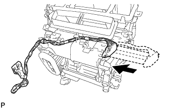 |
Install the quick heater assembly as shown in the illustration.
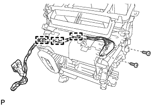 |
Install the 2 screws.
Engage the 3 clamps.
for RHD:
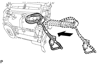 |
Install the quick heater assembly as shown in the illustration.
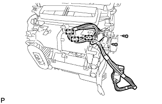 |
Install the 2 screws.
Engage the 3 clamps.
| 10. INSTALL AIR OUTLET CONTROL SERVO MOTOR SUB-ASSEMBLY |
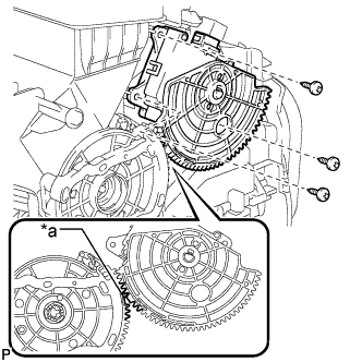 |
Using the reference point, install the air outlet control servo motor sub-assembly with the 3 screws.
| *a | Reference Point |
| 11. INSTALL NO. 2 AIR MIX CONTROL SERVO MOTOR SUB-ASSEMBLY |
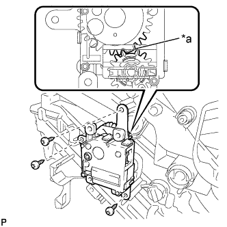 |
Using the reference point, install the No. 2 air mix control servo motor sub-assembly with the 3 screws.
| *a | Reference Point |
| 12. INSTALL AIR MIX CONTROL SERVO MOTOR SUB-ASSEMBLY |
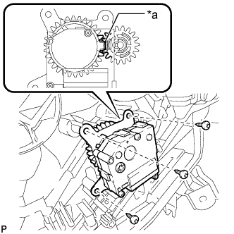 |
Using the reference point, install the air mix control servo motor sub-assembly with the 3 screws.
| *a | Reference Point |
| 13. INSTALL AIR CONDITIONING HARNESS ASSEMBLY |
Connect each connector.
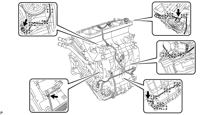
Engage each clamp to install the air conditioning harness assembly.
| 14. INSTALL ASPIRATOR (for LHD) |
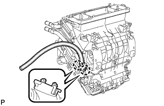 |
Engage the 2 claws and install the aspirator.
| 15. INSTALL ASPIRATOR (for RHD) |
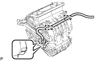 |
Engage the 2 claws and install the aspirator.
| 16. INSTALL NO. 2 AIR DUCT SUB-ASSEMBLY (for LHD) |
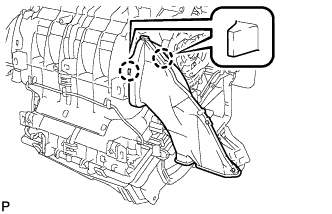 |
Engage the 2 claws to install the No. 2 air duct sub-assembly.
| 17. INSTALL NO. 1 AIR DUCT SUB-ASSEMBLY (for RHD) |
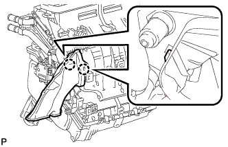 |
Engage the 2 claws to install the No. 1 air duct sub-assembly.
| 18. INSTALL BLOWER ASSEMBLY (w/o PTC Heater) |
Engage the guide.
Install the blower assembly with the 3 screws.
Connect the connector.
| 19. INSTALL BLOWER ASSEMBLY (w/ PTC Heater) |
Engage the guide.
Install the blower assembly with the 3 screws.
Connect the connector.
Engage each clamp.
Install the screw and connect the quick heater connector.
Reattach the felt tape.
