LIGHTING SYSTEM > LVL Terminal Circuit |
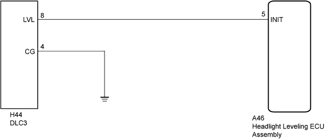
| 1.CHECK HARNESS AND CONNECTOR (DLC3 - HEADLIGHT LEVELING ECU ASSEMBLY) |
Disconnect the A46 headlight leveling ECU assembly connector.
Measure the resistance according to the value(s) in the table below.
| Tester Connection | Condition | Specified Condition |
| A46-5 (INIT) - H44-8 (LVL) | Always | Below 1 Ω |
| A46-5 (INIT) - Body ground | Always | 10 kΩ or higher |
|
| ||||
| OK | |
 |
| 2.CHECK HARNESS AND CONNECTOR (DLC3 - BODY GROUND) |
Measure the resistance according to the value(s) in the table below.
| Tester Connection | Condition | Specified Condition |
| H44-4 (CG) - Body ground | Always | Below 1 Ω |
|
| ||||
| OK | ||
 | ||
| ||

