FRONT AXLE HUB > INSTALLATION

for Preparation Click here


HINT:
  1. Use the same procedure for the RH side and LH side.
  2. The procedure listed below is for the LH side.


1. INSTALL FRONT AXLE HUB SUB-ASSEMBLY
  1. Secure the steering knuckle between aluminum plates in a vise.

    NOTICE:
    Do not overtighten the vise.

  1. Install the front axle hub sub-assembly and front disc brake dust cover with the 4 bolts.

    Torque:
    40 N*m{ 408 kgf*cm , 30 ft.*lbf }


2. INSTALL FRONT AXLE ASSEMBLY
  1. Install the front axle assembly to the front shock absorber with the 2 bolts and 2 nuts.

    Torque:
    240 N*m{ 2447 kgf*cm , 177 ft.*lbf }

    NOTICE:
    When installing the nuts, keep the bolts from rotating.


3. INSTALL FRONT DRIVE SHAFT ASSEMBLY


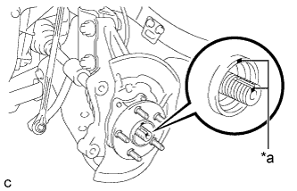
    C205579E02
  1. Align the matchmarks on the front drive shaft assembly and front axle hub sub-assembly and install the front drive shaft assembly to the front axle hub sub-assembly.
    Text in Illustration 
    *a
    Matchmark


4. CONNECT FRONT LOWER NO. 1 SUSPENSION ARM SUB-ASSEMBLY
  1. Install the front lower No. 1 suspension arm sub-assembly to the front lower ball joint assembly with the bolt and 2 nuts.

    Torque:
    89 N*m{ 908 kgf*cm , 66 ft.*lbf }


5. CONNECT TIE ROD END SUB-ASSEMBLY


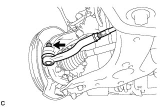
    C151407
  1. Connect the tie rod end sub-assembly LH to the steering knuckle with the nut.

    Torque:
    49 N*m{ 500 kgf*cm , 36 ft.*lbf }

    NOTICE:
    Further tighten the nut up to 60° if the holes for the clip are not aligned.

  1. Install a new clip.


6. INSTALL FRONT DISC


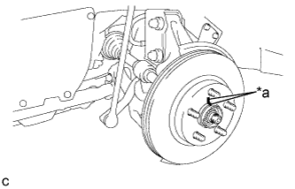
    C205538E04
  1. Align the matchmarks of the disc and axle hub, and install the disc.
    Text in Illustration 
    *a
    Matchmark

    NOTICE:
    When replacing the disc with a new one, select the installation position where the front disc has minimal runout.


7. INSTALL FRONT DISC BRAKE CALIPER ASSEMBLY
  1. Install the front disc brake caliper assembly to the steering knuckle with the 2 bolts.

    Torque:
    137 N*m{ 1394 kgf*cm , 101 ft.*lbf }

    NOTICE:
    Do not twist the flexible hose when installing the front disc brake caliper assembly.


8. TEMPORARILY INSTALL FRONT AXLE SHAFT NUT
  1. Clean the threaded parts on the front drive shaft assembly and a new front axle shaft nut using a non-residue solvent.

    NOTICE:
    1. Be sure to perform this work even when using a new drive shaft.
    2. Keep the threaded parts free of oil and foreign matter.

  1. Using a socket wrench (30 mm), while applying the brakes, temporarily install the front axle shaft nut.

    Torque:
    216 N*m{ 2203 kgf*cm , 159 ft.*lbf }

    NOTICE:
    Stake the front axle shaft nut after inspecting for looseness and runout in the following steps.

    HINT:
    Keep depressing the brake pedal to prevent the drive shaft from rotating.


9. SEPARATE FRONT DISC BRAKE CALIPER ASSEMBLY
  1. Remove the 2 bolts and separate the front disc brake caliper assembly.

    NOTICE:
    Use wire or an equivalent tool to keep the front disc brake caliper assembly from hanging down by the flexible hose.


10. REMOVE FRONT DISC


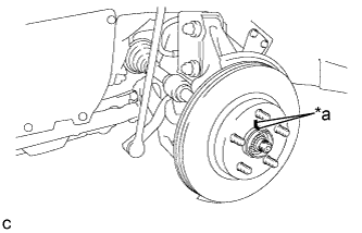
    C205538E03
  1. Put matchmarks on the disc and the axle hub.
    Text in Illustration 
    *a
    Matchmark

  1. Remove the front disc.


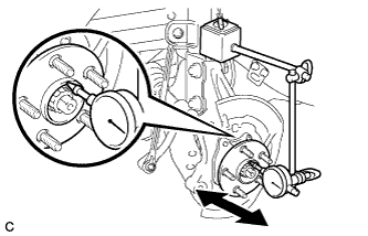
11. INSPECT FRONT AXLE HUB BEARING LOOSENESS


    C205611
  1. Using a dial indicator, check for looseness near the center of the front axle hub sub-assembly.

    Maximum looseness:
    0.05 mm (0.00197 in.)

    NOTICE:
    1. Ensure that the dial indicator is set perpendicular to the measurement surface.
    2. Keep the magnet of the dial indicator away from the front speed sensor.

    HINT:
    If the looseness exceeds the maximum, replace the front axle hub sub-assembly.


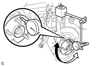
12. INSPECT FRONT AXLE HUB RUNOUT


    C205610
  1. Using a dial indicator, check for runout on the surface of the front axle hub sub-assembly outside the front hub bolt.

    Maximum runout:
    0.05 mm (0.00197 in.)

    NOTICE:
    1. Ensure that the dial indicator is set perpendicular to the measurement surface.
    2. Keep the magnet of the dial indicator away from the front speed sensor.

    HINT:
    If the runout exceeds the maximum, replace the front axle hub sub-assembly.


13. INSTALL FRONT DISC


    C205538E04
  1. Align the matchmarks of the disc and axle hub, and install the disc.
    Text in Illustration 
    *a
    Matchmark

    NOTICE:
    When replacing the disc with a new one, select the installation position where the front disc has minimal runout.


14. INSTALL FRONT DISC BRAKE CALIPER ASSEMBLY
  1. Install the front disc brake caliper assembly to the steering knuckle with the 2 bolts.

    Torque:
    137 N*m{ 1394 kgf*cm , 101 ft.*lbf }

    NOTICE:
    Do not twist the flexible hose when installing the front disc brake caliper assembly.


15. INSTALL FRONT FLEXIBLE HOSE
  1. Install the front flexible hose to the steering knuckle with the bolt.

    Torque:
    19 N*m{ 192 kgf*cm , 14 ft.*lbf }


16. INSTALL FRONT SPEED SENSOR
  1. Install the front speed sensor and front flexible hose to the front shock absorber with the bolt and clamp.

    Torque:
    19 N*m{ 192 kgf*cm , 14 ft.*lbf }

    NOTICE:
    Do not twist the front speed sensor when installing it.

    HINT:
    Install the front flexible hose first and then the speed sensor harness bracket.

  1. Install the front speed sensor to the steering knuckle with the bolt.

    Torque:
    8.5 N*m{ 87 kgf*cm , 75 in.*lbf }

    NOTICE:
    Do not twist the front speed sensor when installing it.


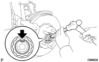
17. INSTALL FRONT AXLE SHAFT NUT


    C068609
  1. Using a chisel and hammer, stake the front axle shaft nut.


18. INSTALL FRONT WHEEL

Torque:
103 N*m{ 1050 kgf*cm , 76 ft.*lbf }


19. CONNECT CABLE TO NEGATIVE AUXILIARY BATTERY TERMINAL
  1. Connect the cable to the negative (-) auxiliary battery terminal (Click here).

  1. Connect the reservoir level switch connector.

  1. Clear the DTCs (Click here).


20. INSPECT AND ADJUST FRONT WHEEL ALIGNMENT
(Click here)


21. CHECK FOR SPEED SENSOR SIGNAL
(Click here)